If you don’t want to use the cumbersome multimeters for tracing out simple faults like short circuits, continuity or resistance inside PCB assemblies and wirings, then perhaps the circuits described in this article are exactly what you need. Find out how to make a continuity tester.
Introduction
Electrical and electronic equipment used in various applications are prone to faults and defects. Most of the time these defects are minor and superficial and are in the form of breaks in the wires, for example a break in the supply line. Since much of this equipment involves a bunch of wires, the fault finding may become pretty tough and difficult to diagnose. However, as usual, electronics technology has a remedy for all problems. The small, inexpensive circuit of a continuity tester may be used to detect such defects and can save you from the unnecessary trouble of uninstalling the entire machinery. In this article we will study a few circuits and learn how to make a continuity tester, but first let’s start with the basics: what exactly is a continuity tester?
What is a Continuity Tester?
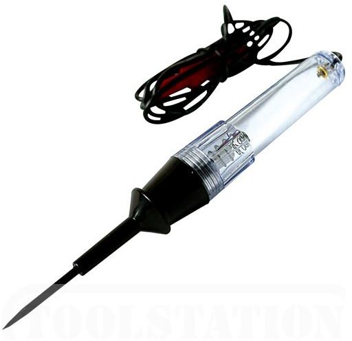
A continuity tester is a simple device consisting of two testing probes and a light (LED) or buzzer indicator. It is used to detect the presence of continuity or a break in between the two ends of a conductor which is connected to its testing probes. For instance, if the two probes of a continuity tester are touched to the two ends of a wire bundle, its indicator may get activated to confirm that there is no interruption in the continuity of the wire and everything’s fine, or, if the indicator shows no action it would mean that there’s a break in the continuity of the wire and needs attention. It may also be used to trace out faults in complicated electronic PCBs, automobile electricals etc.. Since it itself operates at a very low voltage and produces a very high resistance in between its prods, the risk of the sophisticated PCB components getting damaged are eliminated. It is always important to switch OFF the power of the circuit under test, or else the tester may get activated through the power of the circuit and give false alarm.
Make these Simple Circuits for a Continuity Tester
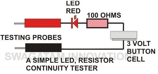
Using only a single LED: A single LED and a resistor may be used to construct a very simple form of continuity tester. Here in presence of continuity in between the two probes, the LED circuit gets completed and it lights indicating that the circuit under test is fine and vice versa.
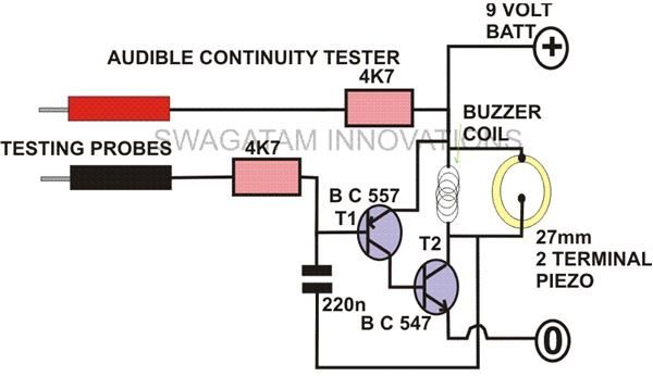
Using Transistors: A very simple yet useful piece of testing equipment can be built using a couple of transistors and few passive components. The circuit basically is an oscillator with a buzzer connected at its output. It will produce a particular audio tone depending upon the resistance of the circuit under test connected across its testing probes. With little practice you should be able to judge the condition of the circuit under test by hearing the frequency of the output tone and should be able to make a difference between a short, continuity and some unwanted resistance in the line. An audible alarm also means that you don’t have to shift your vision from the circuit under test to the continuity tester again and again.
These circuits require hardly any components and thus can simply be constructed over a small square general PCB within no time.
Through these above circuit illustrations you must have easily understood how to make a continuity tester, make one for yourself and see how faithfully it serves the purpose.
Testing Continuity of a Group Of Wires - Cables
Another simple continuity tester design, probably better than the above two, is shown alongside. The circuit can be specifically useful for testing long cables consisting of more than a single core wire or having a group of wires.
The circuit is again very simple, a couple of NPN transistors are configured as a Darlington pair emitter follower circuit to achieve high sensitivity. An LED is used as indicator at the collector of the transistor which lights up when continuity between the ends of the conductor under test is detected.
The circuit may be built over a small general purpose PCB and housed inside an appropriate enclosure along with a 3 volt cell for powering the circuit. The output leads will also need to be terminated appropriately.

The testing of continuity of a group of wires may be done individually using the above circuit in the following manner:
As shown in the figure, consider a cable consisting of four core wires having colors as blue, navy blue, green and brown.
Each wire may be checked individually for continuity, for example beginning with the blue wire the testing may be done by holding one of its stripped ends with your finger and touching the other end of the wire to the base terminal of the circuit (the positive terminal being held with the other hand.)
If the wire is OK, the LED will instantly light up indicating continuity. No response from the LED will indicate a possible break in the continuity of the wire.
Similarly, the other strands may also be verified.
Reader’s Contribution
The above circuit was modified with extra benefits and the prototype built by one of keen Bright Hub readers and hobbyist, Mr. Bobby. The images below show how it’s done.


References
- Authors own experience and expertise


