The circuit design of a simple 12 volt flasher unit described here can be built by you and utilized to flash the indicator lights of your own motor-bike. If looked at from a business point of view, the unit may be mass produced and sold in the market to earn some good revenue.
Introduction
We all must have noticed that every vehicle consists of four distinct orange colored lights at the edge of their four corners. These lights are called indicator lights and are perhaps one of the very important parts of every vehicle as far as safety is concerned.
On a busy street whenever a driver needs to change the course of its vehicle or make a turn (towards left or right), it becomes very important for him to give a prior warning signal to other speeding vehicles from the rear side. This is effectively done by flashing the relevant (left pair or right pair) indicators so that the other vehicles around are intimated of a change in its course and avoid a possible accident.
These indicators are actually made up of 12 volts incandescent bulbs fitted in the appropriate left, right side holders. A 12 volt flasher unit is used to alternately switch these bulbs ON and OFF, thus producing a flashing or blinking effect.
How Do the Flasher Units Operate?
The flasher units which are today commercially available in the market may be technically differentiated into three categories, namely:
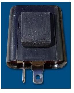
- Electro-Mechanical Flasher: It is normally used only for the 2-wheelers as its power handling capacity is quite limited. It basically consists of a bi-metal strip inside which in effect of a heating coil, alternately makes and breaks the supply to the bulbs, making the bulbs to flash.
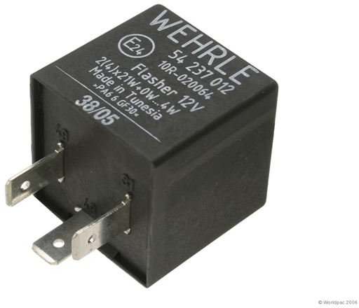
Solid State Electronic Flasher: These types of flashers operate using an electronic circuit. The entire load of the bulbs is handled by a power transistor. The circuit is in fact an oscillator which provides switching pulses to the power transistor. In response to these pulses the power transistor switches the indicator lights ON and OFF alternately producing a blinking effect. Since they do not incorporate any movable part, are generally highly durable. They may come in 2-pin or 3-pin versions and may be universally used for all small vehicles.
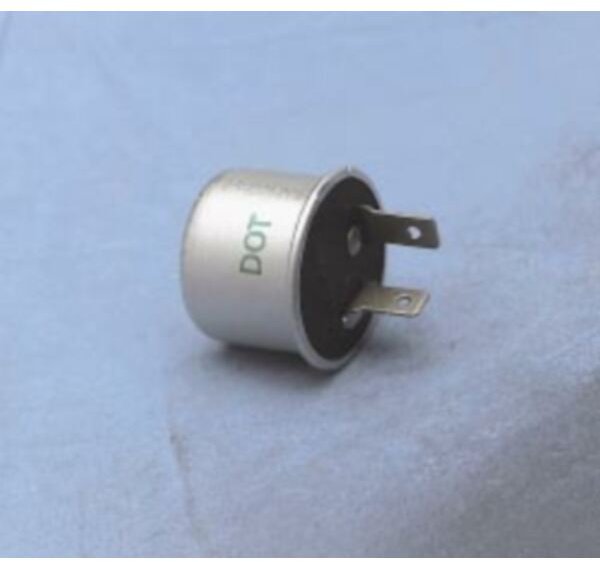
Relay Type Electronic Flasher: In these types of flashers, the relay forms the main load handling component. Again an electronic oscillator is used to drive the relay. The load or the indicator bulbs are connected in series with the relay, therefore when the relay oscillates the bulbs also flash in accordance with the relay contacts and generate the required signaling. These can also be used universally for all vehicles barring the trucks.
About the Present Circuit
The circuit design of a 12 volt flash
er unit presented here is a solid state 2-pin type flasher that may be used for all 2-wheelers.
The circuit utilizes very few components and surely you won’t find a flasher unit more economical than this one. Yet the circuit is highly reliable, long lasting and is almost permanent.
The functioning of the circuit is very basic and may be understood from the following discussion:
-
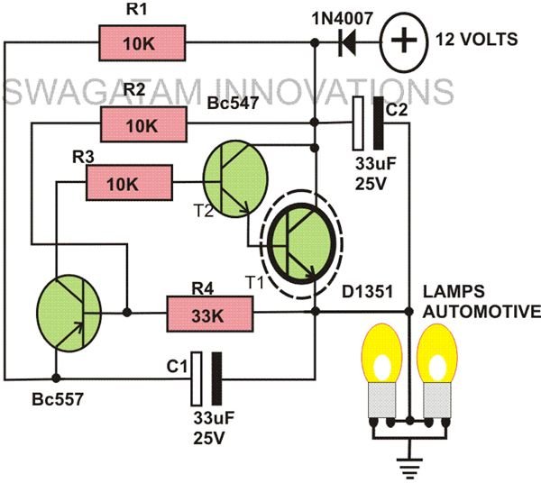
A power transistor T1 along with T2 forms a high power Darlington pair. The PNP transistor T3, along with the capacitor C1 and the associated resistors forms the oscillating elements.
-
When the unit is connected to the flasher socket of a motor-bike and switched ON, initially C1 slowly charges via resistor R1.
-
As soon as it is fully charged (within a second or so, depending upon the value of the capacitor chosen), T3 starts conducting which turns the Darlington pair T1-T2 ON, and thus the Lamps are also switched ON.
-
But due to this, capacitor C1 starts discharging through T1 and R4. Once it is fully discharged T1 cannot conduct, the lamps are extinguished and the cycle repeats all over again producing a cool flashing of the indicator bulbs.
-
Capacitor C2 is kept to filter out the dangerous spikes commonly present in the electrical system of every vehicle when in motion.
-
The value of capacitor C1 may be altered to produce different flashing rates.
The whole unit of this 12 volt flasher unit may be easily constructed with the help of the circuit schematic over a small piece of general PCB and can be finished within half an hour. The initial testing can be simply done using a 12 volt power supply and series automobile bulbs.


