
The simple homemade RFID access control circuit presented here is super simple to build. Once the tuning is completed, the lock will respond only to the particular key matched with the lock.
In one of my previous articles you may have studied the construction of a simple combination lock and its application in restricted areas where only the authorized personnel gets the access control by pressing the assigned code numbers.
The circuit of RFID access control proposed here is really simple to build and has almost the same application specifications. However, its operating procedure is much simpler, since you don’t have to exert extra effort in remembering the codes and spending extra time in pressing them. Just with a flick of a switch of the transmitter (key), the receiver (lock) is turned ON to activate the load.
Building the RFID Unit
The circuit may be divided into two parts, viz. the receiver and the transmitter. Let’s try to understand the construction hints of the receiver circuit first through the below given points:
-
Referring to the circuit schematic, begin the construction by soldering IC 324 somewhere in the center of a general purpose board (size: 3”*2”).
-
Fix the other associated components like the resistors and the capacitors around the IC. Do not crowd them; keep some space in between each of the components.
-
As per the circuit diagram interconnect them with each other and the IC. It is best done by bending their leads to the relevant points and soldering them.
-
Next insert the coil, trimmer and solder them. As explained above, connect them to the appropriate points in the circuit.
The construction details of the coil are explained in the diagram content itself.
Now let’s move on to the transmitter circuit section and discuss the following construction steps:
-
Cut a small piece of general purpose board (size: 1”*1/2”).
-
Insert and solder the transistor exactly at the center of the board.
-
Similarly fix the other components and interconnect their leads in such a way that the connections are neat and very compact.
-
Do not keep the transistor erect; bend its printed surface downwards so that it touches the board flat.
-
Also fit the coil and the push-to-on micro switch in the above method. Solder two small pieces of thin flexible wire; solder them to the supply points of the circuit.
-
Fix the other ends of these wires to a 3V button cell by soldering them permanently.
Circuit Description
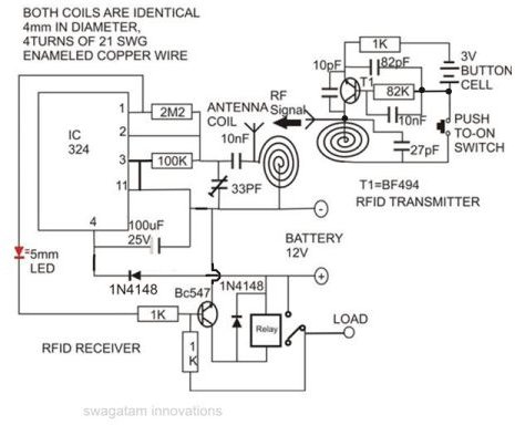
In the present design of RFID for area security management the receiver circuit forms the lock and the transmitter forms the key.
The following explanation of the receiver circuit will give a clear picture of its internal functioning:
-
Only 1 op-amp out of the four in IC 324 has been used here. It performs the function of a strong RF amplifier. The operating principle is same as discussed in one of my previous articles of a ghost detector.
-
The RF signal from the transmitter is received by the antenna coil and is tuned by the trimmer capacitor.
-
The resonated voltage is immediately amplified by the op-amp.
-
Its output triggers the transistor which in turn activates the relay.
-
The relay gets latched instantly through its N/O contacts.
-
Whatever load (12 V) is connected to these contacts is also thus activated.
The transmitter circuit can be easily understood through the following explanations:
-
The RF transistor BF494 and its associated parts together form a high frequency RF signal generator of around 100MHz.
-
As long as the push button is kept depressed the circuit continues to generate the high frequency RF signal through the antenna coil.
Testing Procedure
The testing procedure of the circuit of RFID for area security management is absolutely simple and is completed through the following simple steps:
-
Connect a 12V DC regulated supply to the receiver circuit.
-
Keeping the transmitter circuit’s switch depressed, bring its antenna to a close proximity to the antenna coil of the receiver circuit.
-
Adjust the capacitor trimmer in the receiver circuit till the LED starts glowing brightly and the relay gets energized.
-
The receiver frequency is now matched with the transmitter frequency and will respond only to this particular key.
-
Now releasing the transmitter switch should switch OFF the LED immediately, but the relay should remain latched.
-
Switch the power OFF to reset the relay.
This concludes the testing part. Enclosure of the receiver circuit will depend on its application and the output load connected to it. I will leave it to the readers to decide.
The transmitter may be enclosed in a small match box size box with the switch button and the antenna protruding out of it.
The circuit of this RFID for area security management will find many different applications in the places like jewelers’ shops, factory gates, bungalows, shopping malls, defense areas, etc.
RFID Using a Flip-Flop
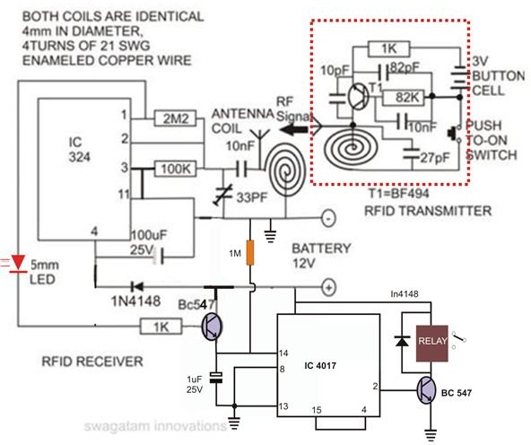
The above discussed circuit idea can be further modified to produce alternate switching of the output in response to the triggered subsequent input signals through the transmitter. The addition of a flip-flop stage enables the functioning of the toggling sequence. The sample circuit diagram is attached alongside.


