Whether indoors or outdoors this high-efficiency inverter can provide clean AC to power all your small appliances like fans, lights, soldering irons, etc.
Operating Principle of an Inverter
An inverter can be taken as a crude form of UPS. Obviously the main use of an inverter is only for powering common electrical appliances like lights and fans during a power failure.
As the name suggests the basic function of an inverter is to invert an input direct voltage (12VDC) into a much larger magnitude of alternating voltage (generally 110VAC or 220VAC).
Before learning how to build an inverter, let’s first understand the following fundamental elements of an inverter and its operating principle:
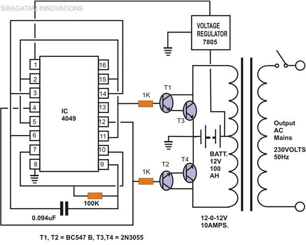
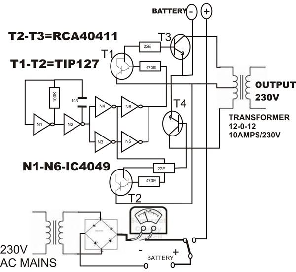
Oscillator: An oscillator converts the input DC (Direct Current) from a lead acid battery into an oscillating current or a square wave which is fed to the secondary winding of a power transformer. In the present circuit, IC 4049 has been used for the oscillator section.
Transformer: Here the applied oscillating voltage is stepped up as per the ratio of the windings of the transformer and an AC much higher than the input DC source becomes available at the primary winding or the output of the inverter.
Charger: During power backups when the battery gets discharged to a considerable level, the charger section is used to charge the battery once the AC mains is restored.
*Disclaimer: This project should be taken on at your own risk and is recommended for those who have experience building their own circuits. Neither the author of the article, nor Bright Hub Engineering bears no responsibility for negative outcomes to this tutorial.
How to Build an Inverter
To clearly understand how to build an inverter, let’s go through the following simple construction details:
-
As per the circuit schematic first complete the assembly of the oscillator section consisting of the smaller parts and the IC. It is best done by interconnecting the component leads itself and soldering the joints.
-
Next fit the power transistors into the appropriately drilled aluminum heat sinks. These are made by cutting an aluminum sheet into the given sizes and bending them at the edges so that it can be clamped.
-
Do not fit the transistors directly on to the heat sinks. Use mica isolation kit to avoid direct contact and short circuiting of the transistors with each other and the ground.
-
Clamp the heat sink assembly to the base of a well ventilated, sturdy, thick gauge metallic enclosure.
-
Also fix the power transformer beside the heat sinks using nuts and bolts.
-
Now connect the appropriate points of the assembled circuit board to the power transistors on the heat sinks.
-
Finally join the power transistor’s outputs to the secondary winding of the power transformer.
-
Finish the construction by fitting and interconnecting the external electrical “fittings” like fuses, sockets, switches, mains cord and the battery inputs.
-
An optional separate power supply circuit using a 12V/3Amp. transformer may be added inside to charge the battery whenever required (see diagram).
Circuit Description
To better understand how to build an inverter, it is important to learn how the circuit functions through nthe following steps:
-
Gates N1 and N2 of IC 4049 are configured as an oscillator. It performs the primary function of supplying square waves to the inverter section.
-
Gates N3… N6 are used as buffers so that the circuit is not load dependant.
-
Alternating voltage from the buffer stage is applied to the base of the current amplifier transistors T1 and T2. These transistors conduct in accordance with the applied alternating voltage and amplifies it to the base of the output transistors T3 and T4.
-
These output power transistors oscillate at a full swing, delivering the entire battery voltage into the each half of the secondary winding alternately.
-
This secondary voltage is induced in the primary winding of the transformer and is stepped-up into a powerful 230 volts (AC). This voltage is used to power the output load.
Testing Procedure
You can further understand how to build an inverter by concentrating on the following testing procedure given in a step-by-step manner below:
-

Begin the testing procedure by connecting a 100 watt bulb at the output socket of the inverter
-
Insert a 15 Amp./12V fuse inside the fuse holder
-
Finally connect a 12V automobile battery to the battery inputs of the inverter.
-
If all the connections are right, the 100 Watt bulb should immediately light up brightly.
-
Keep the inverter ON for an hour and let the battery discharge through the bulb
-
Then shift the given toggle switch to the charging mode, check the meter reading,
-
The meter should indicate the charging current of the battery.
-
The meter reading should gradually die down to zero after a span of time, confirming that the battery is fully charged and ready for the next cycle.


