A machine cycle plays an important role in the concept of timing diagram. Learn about the various types of machine cycle with detailed and diagrammatic explanation.
Introduction
In the previous article we discussed about the Opcode fetch cycle, memory read and I/O read cycles. In this article let us discuss the various other types including the memory write cycle and I/O write cycle.
Memory Write Machine cycle
This cycle as the name specifies is used for sending data from the registers of the microprocessor to the memory or any other I/O devices.
A simple example for such an instruction is MOV M, A
When the above instruction is executed the contents of the accumulator is moved to the specified memory location. For this operation to take place, we need two machine cycles. One is the Opcode fetch cycle and the second to transfer the contents of memory to the accumulator.
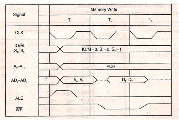
T1 State:
This is the Opcode fetch cycle where the microprocessor places the 16 bit address on the higher order address bus (A8-A15) and lower order address and data multiplexed bus (AD0-AD7). The ALE goes high to latch the AD0-AD7 bus and during the middle of T1 state it goes low, so that the complete 16 bit address is available.
Now what the microprocessor has to do with this address and data? Should it write the data or read it? How will the microprocessor recognize about what operation should be performed?
The microprocessor can recognize it using the status signal IO/M’, S0 and S1. For memory write cycle the values of status signals should be
IO/M’= 0
S1=0
S0=1
This status information is always maintained throughout the machine cycle.
T2 State:
At the beginning of this state WR’ goes low (as it is a memory write cycle). Whereas in read cycle the RD’ goes low to enable memory. During this state the contents of the register is placed on the Data bus.
T3 State:
The data which was placed on the data bus in the previous state is now transferred to the specific memory location. In the middle of this state the WR’ goes high and disables the memory.
Thus the data is transferred from the accumulator to specific memory location. This is the memory write machine cycle.
For better understanding the diagram of memory write machine cycle is shown below.
I/O Write Machine Cycle
In the previous article we saw memory read and I/O read. Both operations are similar to each other.
Similarly the memory write and I/O write operations are similar to each other.
Example of I/O write machine cycle is OUT 23H
When the above instruction is executed, the data is transferred from accumulator to the specified location of the output device (in this case it is 23H). The microprocessor recognizes the I/O write machine cycle from the status signals IO/M’=1, S0=1, S1=0.
In the I/O write machine cycle, external latching using ALE is not necessary. This is because in this machine cycle, the address is duplicated and is available on the address bus till the end of the machine cycle.
INTA Machine Cycle
Before dealing with the INTA machine cycle, first we must know what INTA is. INTA is the Interrupt acknowledge signal.
When microprocessor executes an instruction or a program, it checks the INTR during the execution of each instruction. When the INTR is low, the program execution continues. But when the INTR goes high, the microprocessor completes the execution of current instruction and sends an Interrupt acknowledge signal (INTA). The microprocessor now saves the address of the next instruction to be executed in the stack. After this step, the microprocessor finds the cause for which it was interrupted and then return to the program which it was executing before the INTR signal. These operations come under the INTA machine cycle.
Bus Idle Machine Cycle
When we discussed about the basics of timing diagram and timing diagram of various signals, we often came across one phrase “BUS IDLE MACHINE CYCLE”.
So what exactly is this bus idle machine cycle?
A bus idle machine cycle is a cycle during which the Data bus of the microprocessor is not in use. That is the Data bus is in IDLE state. When the Bus idle machine cycle takes place, the following events can be observed
No wait cycles are possible
No memory or I/O device communicates with the microprocessor.
The data bus is not used.
Thus we have successfully discussed the various types of machine cycles present in an 8085 microprocessor.
Image Courtesy
Microprocessor and it applications by “Manoharan”


