It is possible to convert a SR and JK flip-flops into T flip-flops just be adding few gates or by giving some extra connections.
Introduction
In the previous articles we have already discussed about the conversion of RS flip-flop into a D flip-flop and converting an SR flip-flop into JK flip-flop. In this article let us discuss about the conversion of RS and JK into a T flip-flop. Let us now learn about creating T flip flop circuits by conversion from other types.
SR Flip-flop to T flip-flop
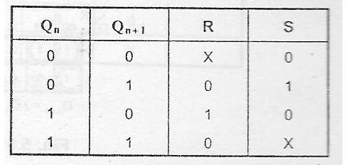
We know that the SR flip-flop has four different transitions from the present state to next state. The four transitions are 0 to 0 transition, 0 to 1 transition, 1 to 0 transition and 1 to 1 transition.
0 to 0 transition occurs when S=0 and R=X. where X denotes don’t care condition. In other words the value of R may be either 1 or 0 and it will not affect the state of the system.
0 to 1 transition occurs when S=1 and R=0.
1 to 0 transition occurs when S=0 and R=1.
1 to 1 transition occurs when S=X and R=0.
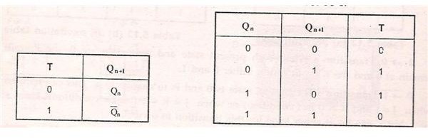
But T flip-flop has only one input T. From the truth table of T flip-flop it is evident that, When the T input is 1, the present state of the system is complemented. In other words, When the T input is 1, the state of the flip-flop is complemented and when T input is 0, the state of the flip-flop is retained.
Now we know that when T=0, the state of the flip-flop remains unchanged. Therefore we can deduce that for 0->0 transitions and for 1-> 1 transition, T must be 0. While for 0->1 transition and for 1-> 0 transitions, T must be 1.
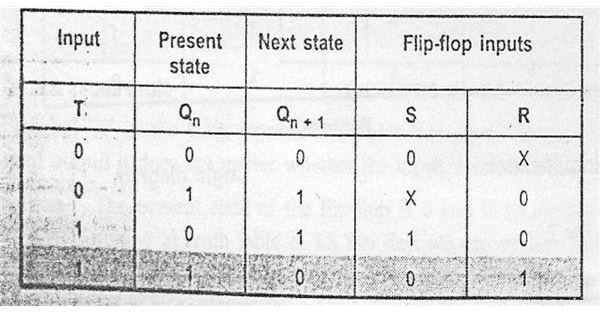
Now from the SR excitation table and T excitation table, we can deduce the excitation table for the conversion of SR flip-flop to T flip-flop.
0-> 0 transitions: For 0 to 0 transitions to occur, the value of T input should be 0 and the value of R and S inputs should be S=0 and R=X.
0-> 1 Transition: For 0 to 1 transition to occur, the input for T flip-flop should be T=1 and for SR inputs S=1 and R=0.
1->0 transition: For 1 to 0 transition to take place, the T input should be equal to T=1 and S=0 and R=1.
1->1 transition: For 1 to 1 transition to take place, T=0 and S=X and R=0.
From the above excitation table draw 2 separate K-map for S and R inputs respectively, with T and Q (n) as the parameters. Q (n) is the present state of the flip-flop.
When T=0 and Q (n) =0 the value of S is 0 and the value of R is X. Similarly complete the K-map for different values of T and Q (n).
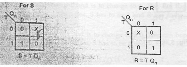
Form the characteristic equation relating S and R inputs to T input. From the K-map we can deduce two characteristic equations
S=T.Q’ (n), where Q’ (n) is the complement of present state Q (n)
R= T. Q (n), where Q (n) is the present state of the system.
From this characteristic equation we can draw the logic diagram for the conversion of RS flip-flop into T flip-flop.
From logic diagram we can see that two AND gates are used along with S and R inputs to form the T input. Thus the conversion of SR flip-flop into T flip-flop takes place.
JK Flip-flop to T flip-flop
This conversion is very similar to the conversion of SR flip-flop to T flip-flop. Here instead of S and R inputs, the values have to be replaced by J and K values.
We know that 4 different transitions takes place in JK flip-flop.
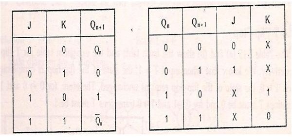
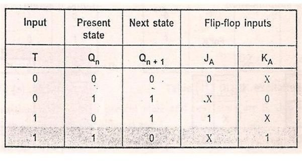
From the T-excitation table and JK excitation table, we can form a new excitation table for the conversion of JK flip-flop to T flip-flop.
When 0 to 0 transition takes place, the value of T input is 0 and the value of J and K inputs are J=0 and K=X. Where X represents don’t care condition.
When 0 to 1 transition takes place the value of T is 1 and the value of J=1 and K=X.
When 1 to 0 transition takes place, the value of T input is 1 and the value of J=X and K=1.
When 1 to 1 transition takes place the, the value of T input is 0 and the value of J and K inputs are J=X and K=0.
From the excitation table, we can form 2 separate K-maps for J and K inputs respectively with T a Q (n) as parameters.
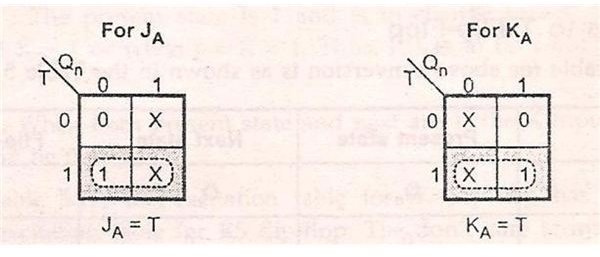
From the K-Map, we can form characteristic equations. They are
J=T, J input is equal to the T input
K=T, K input is equal to the T input.
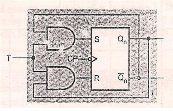
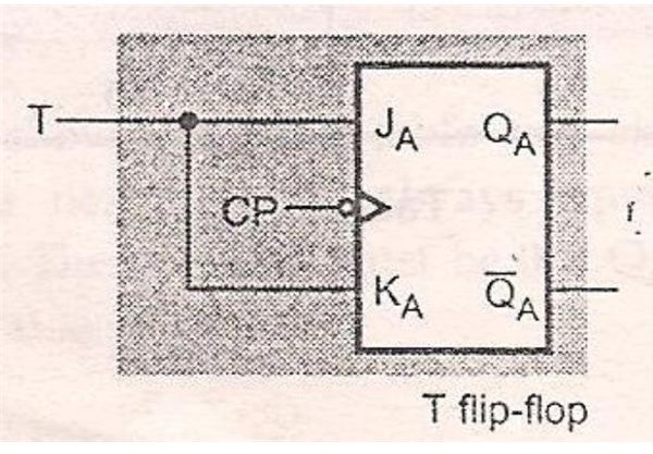
From the K-map we can form the Logic diagram and it is evident from the logic diagram and characteristic equation that J and K inputs are replaced by T input along with clock pulse.
In the next article let us discuss the conversion of JK flip-flop to D flip-flop and T flip-flop to D flip-flop.


