A slip ring motor or a phase wound motor is an induction motor which can be started with full line voltage, applied across its stator terminals. The value of starting current is adjusted by adding up external resistance to its rotor circuit. Read here to find out how the speed control is achieved
Introduction
In my previous article, we have seen about the slip ring induction motor construction and its starting methods. After understanding the basic principle of operation, it is always easier to understand the speed control of slip ring induction motors. We know that the slip ring induction motor has a better starting torque when compared to a squirrel cage induction motor. In this article, we will learn about the speed control of slip ring induction motors and will appreciate that the speed control of slip ring motors are so flexible when compared to the squirrel cage induction motors.
Slip Ring Motor Characteristics
A slip ring motor or a phase wound motor is an induction motor which can be started with full line voltage, applied across its stator terminals. The value of starting current is adjusted by adding up external resistance to its rotor circuit. Incase of a squirrel cage induction motor, the value of rotor resistance is very low, which leads to heavy starting current requirement. But in case of slip ring motors, the rotor resistance is increased by the addition of external resistance. This external resistance makes the rotor circuit current low and thus the stator current drawn is also low with a high starting torque. The point to be noted is the “slip necessary to generate maximum torque is directly proportional to the rotor resistance.” So it is evident that the slip increases with increase in external resistance. With the above statements, let us discuss the different methods of speed control of slip ring induction motors.
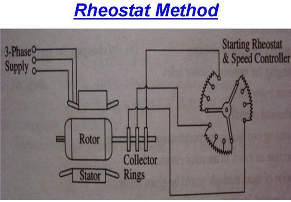
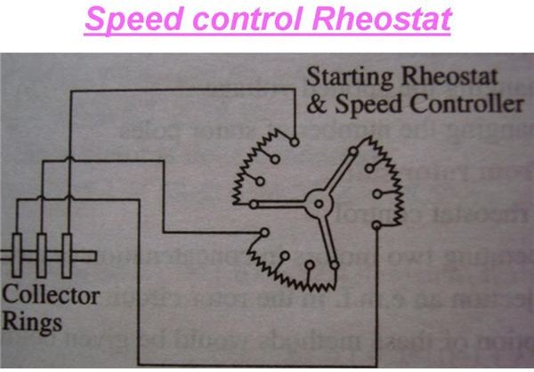
Rotor Rheostat Control
The external rheostat which is used for the starting purpose of these slip ring motors can be used for its speed control too. But the point to look into is the starting rheostat must be rated for “continuous” operation. We have already discussed about the rheostat starting of slip ring motors. With the same rheostat added to the rotor circuit, it is possible to regulate the speed of slip ring motors. The resistance is engaged maximum during starting and slowly cut-off to increase the speed of the motor. When running at full speed, if the need arises to reduce the speed, the resistance is slowly added up and thus speed reduces. To understand the speed control, let us look into the torque-slip relation given below.
Torque T = S/R.
Where S – is the slip of the motor,
And R – is the Rotor resistance
It is evident from the above relation that as the rotor resistance increases, the torque decreases. But for a given load demand, the motor and thus the rotor has to supply the same torque without any decrease. So in order to maintain the torque constant, as the rotor resistance increases the slip also increases. This increase in slip is nothing but decrease in motor speed.
But there are some disadvantages in this method of speed control. As the rotor resistance is increased, the “I^2 * R” losses also increases which in turn decreases the operating efficiency of the motor. It can be interpreted as the loss is directly proportional to reduction in speed. Since the losses are more, this method of speed reduction is used only for short period only.
Cascade Control
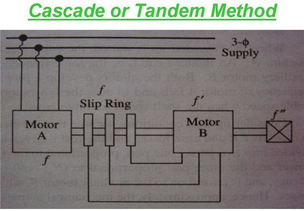
This method has two motors mounted on same shaft called in tandem or cascade operation. The motor “A” which is connected to the mains is called as the main or the master motor. This motor has slip rings mounted on its rotor shaft from which the motor “B” gets its supply from is called as auxiliary or the slave motor. It is to be noted that both the motors are mounted on same shaft. Thus it is evident that either the motors must run at same speed or it may have some gear arrangements.
The main motor is necessarily a slip ring induction motor but the auxiliary motor can be slip ring or squirrel cage induction motor. For satisfactory operation, motor “A” must be phase wound/ slip ring type with the stator to rotor winding ratio of 1:1, so that in addition to cascade operation, they can also run from supply mains separately. Since the supply for the slave motor is from the slip rings of the master motor, and it is forming a chain of sequential operation, the system is called as “Tandem or Cascade or Concatenation” operation. Three or four different combinations are possible for attaining different speeds.
-
Main motor may be alone on the mains, where Na = 120f/Pa, where Pa is the number of poles in motor “A.”
-
Auxiliary or the slave motor running alone on the mains, where Nb = 120f/Pb, where Pb is the number of poles in motor “B.”
- The combination may be in cascade operation. In this operation, the important point is that the phase rotation of the stator fields of the motors “A” and “B” must be in same direction. Thus the synchronous speed of this cascaded motor set is given by Nc = 120f/ (Pa + Pb).
In my next article, we will discuss on the cascade set starting phenomena and speed control by injecting e.m.f in the rotor circuit.
Reference:
Electrical Machines By P.K.Kumar


