Do you know that a Synchronous Motor is electrically identical with an alternator or A.C. Generator? It can operate at a very high efficiency even at 300 r.p.m. Know everything about these motors in this article
Introduction
We have learnt about the various types of electric motors in our previous article. Now we will start to learn about these motors individually. In this article we will take a look at the synchronous motor theory of operation and its working.
The main principle is same as applicable for all motors. It is the mutual induction between the stator & rotor windings which make any motor operational. Also when a 3 phase winding is fed with a 3 phase supply, then a magnetic flux of constant magnitude but rotating at Synchronous speed is produced.
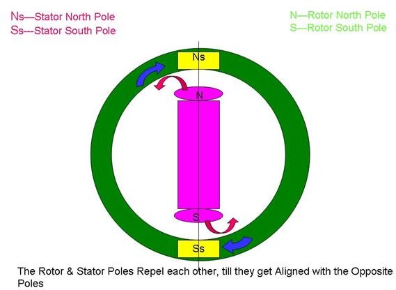
To understand the working of a Synchronous Motor easily, let us consider only two poles in the stator and rotor. With reference to the figure, the stator has two poles Ns & Ss. These poles when energised, produces a rotating magnetic field, which can be assumed that the poles themselves are rotating in a circular manner. They rotate at a synchronous speed and let us assume the direction of rotation to be clockwise. If the rotor poles are at the position shown in the figure, we all know that “Like poles repel each other”. So, the North Pole in the stator repels the north pole of the rotor. Also the south pole of the stator repels the south of the rotor. This makes the rotor to rotate in anti-clockwise direction thus, half a period later, the stator poles interchange themselves, thus making them get aligned with “unlike poles” which attracts each other. I.e. the South Pole of the stator & the North Pole of the rotor gets attracted and get magnetically interlocked.
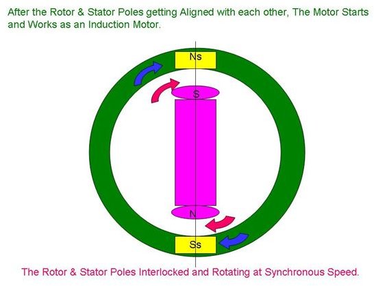
At this position the poles Ns attracts S and poles Ss attracts N. These opposite unlike poles of the rotor & stator start rotating in the same direction as the stator poles. This makes the rotor to rotate unidirectional and at a synchronous speed which is the same speed of rotation of the stator poles. Thus as the position of the stator poles keep changing with a rapid speed and reversal, the rotor poles also rotate and reverse as same as the stator thus causing the rotor to rotate at a constant, synchronous speed and in the same direction.
Theory of operation
When the motor is supplied with a.c. power supply, the stator poles get energised. This in turn attracts (opposite) the rotor poles, thus both the stator and rotor poles get magnetically interlocked. It is this interlock which makes the rotor to rotate at the same synchronous speed with the stator poles. The synchronous speed of rotation is given by the expression Ns=120f/P.
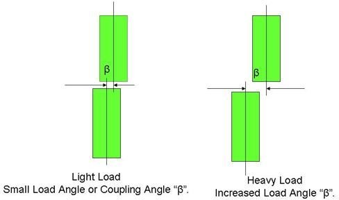
When the load on the motor is increased gradually, the rotor even though runs at same speed, tends to progressively fall back in phase by some angle, “β”, called the Load Angle or the Coupling Angle. This Load angle is dependent on the amount of load that the motor is designed to handle. In other words, we can interpret as the torque developed by the motor depends on the load angle, “β”.
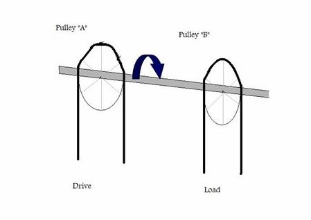
The electrical working of a Synchronous Motor can be compared to the transmission of power by a mechanical shaft. In the figure are shown two pulleys, “A” & “B”. Pulley “A” and the pulley “B” are assumed to be keyed on the same shaft. Pulley “A” transfers the power from the drive through the shaft, in turn making the pulley “B” to rotate, thus transferring power to the load.
The two pulleys which are keyed to the same shaft can be compared to the interlock between the stator & rotor poles.
If the load increases, the pulley “B” transfers the increase in load to the shaft, which is exhibited by the twisting of the shaft.
Thus the twist of the shaft can be compared to the rotor falling back in phase with the stator.
The twist angle can be compared to the load angle “β”. Also when the load increases, the twisting force and the twist angle increases, thus the load angle “β” also increases.
If the load on the pulley “B” is increased to such an extent that it makes the shaft to twist and break, then the transmission of power through the shaft stops as the shaft is broken. This can be compared with the rotor going out of synchronism with the stator poles.
Thus Synchronous motors can run either at synchronous speed or they stop running.
Starting procedure
All the Synchronous Motors are equipped with “Squirrel Cage winding”, consisting of Cu (copper) bars, short-circuited at both ends. These windings also serve the purpose of self-starting of the Synchronous motor. During starting, it readily starts and acts as induction motors. For starting a Synchronous motor, the line voltage is applied to the stator terminals with the field terminals (rotor) left unexcited. It starts as an induction motor, and when it reaches a speed of about 95% of its synchronous speed, a weak d.c excitation is given to the rotor, thus making the rotor to align in synchronism with the stator.( at this moment the stator & rotor poles get interlocked with each other & hence pull the motor into synchronism.
Hunting/Surging/Phase Swinging
Hunting or Surging or Phase swinging of a synchronous motor is caused by either
- Varying load.
- Pulsating supply frequency.
When a Synchronous motor is loaded (such as compressors, pumps, shears etc), as the load increases, its rotor falls back by a coupling angle “β”. As the load is increased further, this angle “β” further increases to cope up with the increased load. At this situation, if the load suddenly decreases, the rotor overshoots and then it’s pulled back to suite the new load on the motor. In this way, the rotor starts oscillating like a pendulum, about its new position corresponding to its new load, trying to regain equilibrium. If the time period of these oscillations happen to coincide with the natural frequency of the machine, then a resonance is set-up, thus may throw the machine out of synchronism. To dampen such oscillations, “damper” or “damping grids” known as “squirrel-cage windings” are employed.
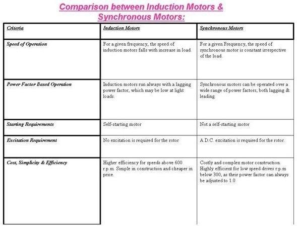
Comparison between Induction Motors & Synchronous Motors:
Applications of Synchronous Motors:
- These motors are used as prime movers (drives) for centrifugal pumps, belt-driven reciprocating compressors, Air Blowers, Paper Mills, rubber factories etc, because of their high efficiency & high speeds (r.p.m above 600).
- Low speed Synchronous motors (r.p.m below 600), are widely used for driving many positive displacement pumps like screw & gear pumps, vacuum pumps, chippers, metal rolling mills, aluminium foil rolling machines etc.
- These motors are also widely used onboard ships. The ship’s navigational equipments like Gyro-compass use a special type of synchronous motor. They are also used as prime movers for Visco-Therm or Viscometer, a device for measuring/regulating the viscosity of the main propulsion engine’s fuel oil.
- Most of the factories & industries use infinite number of inductive loads. These may range from the tube lights to high power induction motors. Thus these inductive loads have a drastic lagging power factor. An Over-excited Synchronous motor ( a Synchronous Capacitor), having a leading power factor, is used to improve the power factor of these supply systems.
- These Motors are also used for Voltage-regulation, where a heavy voltage dip/rise occurs when a heavy inductive load in put on/off at the end of the long transmission lines.
- Synchronous motors can be run at ultra-low speeds by using high power electronic converters which generate very low frequencies. Examples of these motors are a 10 MW range used for driving crushers, rotary kilns & variable speed ball mills.
Credits
Transformers and Motors by George Shultz
Image credits
Personal


