You may be a good bicycle rider, but wouldn’t you love to know how fast you really ride? The article presents an easy electronic circuit which can be integrated to your existing bicycle dynamo to get an instant LED illuminated speed indications, the moment you start peddling.
We all have probably ridden bicycles at some stage of our life and admired their usefulness. Bicycles are favorites especially among the kids who love not only riding them but also decorating the vehicle with many fancy accessories.
Some children are more tech-oriented and prefer the gadgets attached to make their bicycles look more innovative and futuristic. These gadgets are mostly inspired from the ones which are found with power vehicles like motorcycles, cars, etc. Having some sort of lighting arrangement with bicycles is in fact quite common, rather mandatory equipment in some countries, however, a speedometer is something that’s out of the blue and usually never seen anywhere as far as bicycles are concerned.
The present design of a bicycle speedometer system discussed will certainly impress and intrigue the many techno-freaks.
Let’s learn how we can build and install the device in our existing bicycle.
As the name refers to a vehicle speedometer is a device which indicates the speed at which the particular vehicle is moving, which is directly proportionate to the rotational movement of its wheels. It’s obvious that the system would require some sort of stage comprising a device which would translate the wheels rate of movement linearly to corresponding voltage levels, or alternatively the rate of rotations could be counted through some optical or magnetic device.
The second option is rather more complicated and may involve complex opto-coupler/LED assemblies or costly and much complicated Hall-effect sensor assemblies. Converting the rotations into corresponding levels of voltages looks simpler and feasible, as it could be done using an ordinary bicycle dynamo.
A bicycle dynamo basically consists of coils and magnets arranged in such a way that when the central shaft is rotated, voltage is induced in the coils due to the influence of cutting magnetic fields. The magnitude of this voltage is directly proportional to the speed at which its shaft is rotated.
Generally, these dynamos are claw-poled type of electric generators, designed for low RPM applications. We have seen the use of the sidewall running, bottle-type dynamo being used in bicycles for many years which today have been replaced by much more efficient hub dynamos.
In our design, the specification or type of dynamo is not critical; anything that’s able to generate from 1 to 6 volts of power corresponding to slow and maximum peddling speeds respectively is all that is required here.
The bicycle speedometer design presented here uses the above voltage range, which is processed and fed to an electronic circuit for converting the levels into a visible LED bar graph indications.
Parts Required
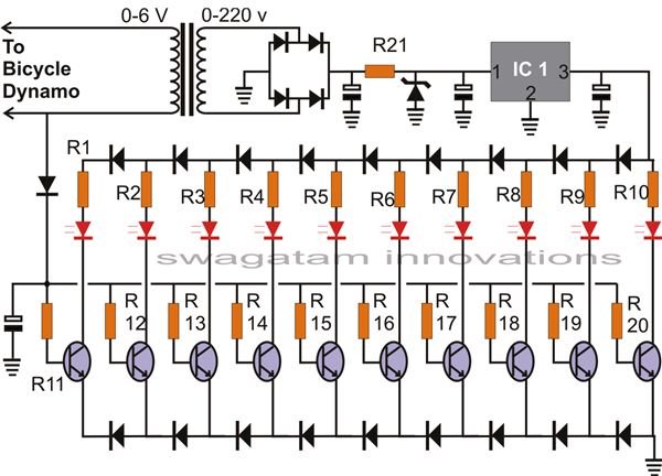
All resistors are 1/4 watt, 5 %, CFR, unless, otherwise stated.
R1 to R10 = 100 Ohms,
R11 to R20 = 10 K,
R21 = 100 Ohms, 1 Watt, Wire Wound,
All diodes are 1N4148,
Zener diode = 20 volts, 1 watt,
All Capacitors are 100 µF / 25 V
IC1 = 7812,
All LEDs are RED 5 mm, preferably high bright, transparent, lens type.
All transistors are BC547 B or any other equivalent type,
Transformer = ordinary 0 – 6 V, 500 mA,
PCB = Genaral Purpose (Veroboard),
Box = Suitable type which can be easily fixed over the handle of the bicycle.
Circuit Description
A bicycle dynamo would ideally produce anything between 1 and its maximum rated output even with optimum rotations of its wheel. With our prototype it would mean a voltage level of not more than 5, with you going at racing speeds. This also means that at relatively slower speeds the voltage would hardly reach over 3, definitely not enough to drive an electronic circuit comprising LEDs as indicators. We need a good 12 volts for driving the LEDs to optimum brightness and make the circuit function as desired with the proposed functioning. The problem is easily solved by using a small transformer commonly used in AC/DC adapters.
Normally these transformers are used in the step down mode where mains AC is lowered through induction at the secondary section to the specified potentials.
The same transformer can also be used in the opposite mode, that is for stepping up a sample voltage by just reversing the input supply.
In our circuit the dynamo voltage is applied to the transformer’s “secondary” winding and a proportionate high voltage of 230 or 120 (as per selected type) is received at the “primary” section of the transformer.
This voltage being too high and “AC” needs to be lowered and rectified. The bridge network and the associated circuit along with the IC 7512 help to generate a stable DC for the circuit even when the cycle is being driven at much lower speeds.
The above voltage is required to keep the circuit “alive” through the range of the speeds generally available with a bicycle, however the actual sample varying voltage which must be sensed by the circuit is applied to the base of the transistors and is derived directly from the dynamo.
Depending upon the varying levels of the above voltage, the transistors conduct in sequence, illuminating the LED array one by one. The 1N4148 diodes inserted in series with the LEDs and the transistor emitters all ensure that the LED switching are well separated and the illuminations shift proportionately with every increment of 0.6 volts from the dynamo.
This bicycle speedometer circuit does not require any prior calibration, all parts are adequately matched for producing the discussed results and do not require initial setup.
References
- Authors own experience.
- Image Credit - Drawn by the author.


