Building virtually any electronic circuit from these small signal transistors and their complementary pairs may be feasible. This goes to show just how versatile and important these devices can be.
A BC547 transistor is a tiny three terminal device capable of converting small signal inputs into large amplified outputs, probably one of the greatest inventions of mankind so far. Even the most sophisticated chips to date have (millions of) transistors embedded within them and configured into complex circuits, assigned with many discrete and specific operations through different stages.
All transistors basically function in the same manner. They are broadly distinguished by their power ratings or power handling capacities. They may be also classified by their frequency handling capabilities and their amplification determining factor or hFE.
A BC547 is a general purpose, small signal transistor fit for almost all types of circuit applications and therefore extensively used for making an unlimited range of electronic gadgets today. Companies like NXP, PHILIPS, Micro Electronics, and FAIRCHILD, to name a few, are the leaders in manufacturing this device.
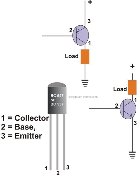
The diagram shows the basic appearance of the transistor, which might differ slightly depending upon the particular make, however the technical specs and the pin-out assignments remain identical.
BC546, BC547, BC548, BC549, BC550, BC556, BC557, BC558, BC559, BC560 Transistors
They all basically come under one roof, but are the “brothers” and the “sisters” of BC547, with the latter being the most commonly used.
BC546, BC547, BC548, BC549 and BC550 are NPN types, while BC556, BC557, BC558, BC559 and BC560 are PNP types and form complementary pairs with the NPN type. You may refer to the article 100 Watt transistor amplifier to see an example of the role of complementary transistor pairs in making a particular circuit more efficient.
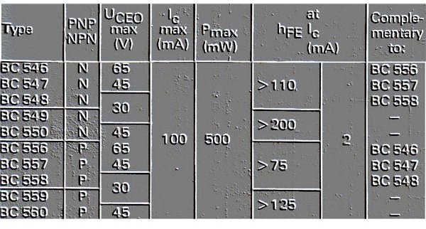
Other than being NPN and PNP types, the above groups also differ with their rating, so the data given here relates to many details of each device.
UCEO refers to the maximum potential difference that can be applied across the collector/emitter terminals of the particular transistors; as an example, BC547cannot hold more than 45 volts, therefore this voltage becomes its maximum safe operating voltage, which must be incorporated with its collector load.
I(max) is the maximum tolerable current that can loaded across the collector/emitter pin-outs of the devices. Here it’s 100 mA for all. Though, this value is the breakdown limit, above which the part may just burn off, it may be noticed that the transistors start heating up well inside the reach of this limit, probably around 70 mA. Thus it’s advised to operate them at around half the value of their individual I(max) ratings.
P(max) is the maximum power handling capacity of the devices, or the load rating which can be connected across its collector/emitter. This value quite corresponds to I(max) and are interconnected. P(max) here is 500 mW or half watt for the entire group.
The table also shows the respective hFE estimations, our BC547, in general may have hFE rated over 100, however the sub-categories with an extra suffix “B” or “C” indicate the device’s enhanced hFE ratings, so a BC547B may have hFE levels well above 200 and maximum up to 500, similarly a BC547C may begin with a level of 400 and cross well over 600.
An increase in the hFE level simply attributes the particular device with more sensitivity, which means it can be triggered with minute base currents, yet switch heavier loads across its collector.
The above criteria concerning a BC547 are the important ones and probably sufficient for helping new users during their construction projects, The following section shows some fundamental rules and hints apply these devices into simple electronic circuits.
As shown in the figure below, consider you have a single BC547 transistor. What could you build using it to make it perform something substantial? You will need to make an initial platform or a basic set-up and then make it work as desired.
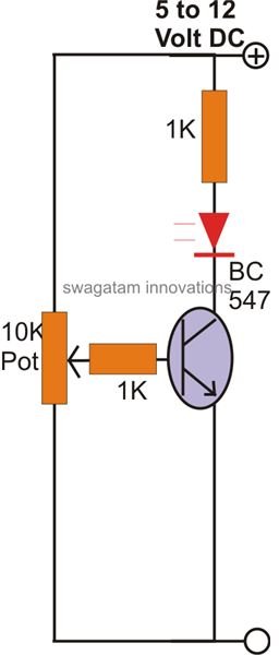
As shown in the figure, connect a resistor of some minimum safe value to the base of the transistor, say a 1 K resistor, this will ensure that at least the device cannot get damaged through its “base” pin-out, because the resistor will never allow the relevant currents to develop to dangerous levels across the vulnerable base/emitter junction of the transistor.
For testing the basic working pattern of the transistor, you would further need to fix a pot along the “base”, positive and the negative terminal.
Next, connect an LED and a resistor to the collector of the transistor, with the help of the diagram. The LED will provide you with immediate visual information regarding the happenings with the circuit. The collector resistor again ensures that the UCEO is kept within the specified limits, safeguarding the transistor as well as the LED.
Initially keep the pot’s knob somewhere at the midway of its rotation. Apply a DC potential across the shown terminals, and you will find the LED coming ON immediately. This happens because a small part of the voltage reaches the base of the transistor and switches ON its collector to ground and allows the voltage to complete, illuminating the LED.
Now adjusting the pot’s slider arm more towards the ground, you’ll find, makes the LED gradually dim, and ultimately switch OFF, at some particular point of the pot setting. This happens because the required magnitude of base potential, instead of reaching the transistor gets grounded through the pot.
This circuit uses an NPN transistor. With a PNP transistor (e.g. BC557), the conditions simply reverses, i.e. the transistor’s emitter connects to the positive, LED/resistor assembly connects across the collector and the ground, and, initially the LED remains switched OFF and gradually comes ON as the pot’s slider arm is gently moved more toward the ground and vice versa. That’s why a BC547 and BC557 are taken as complementary pairs having complementing reverse order performance.
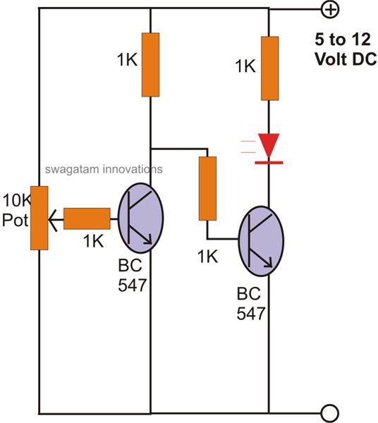
Combining a couple of NPN or, NPN and PNP transistors, can be used for producing more interesting and complex circuit assemblies. If another NPN stage is introduced after the above discussed circuit (see figure), the circuit produces the opposite results: initially the LED remains switched but switches ON when the pot is moved in the above manner. However, here the switching transitions are quick with minimum hysteresis making the unit more accurate than a single transistor version.
A complementary pair circuit using PNP/NPN devices also presents us with some useful circuit arrangements. The above transistor features can be successfully implemented for many different circuit applications.
I have already discussed a huge number of BC547 simple circuit configurations. You may like to refer to them through this article and understand how the above properties are simply exploited, and also you might want to develop your own ideas and learn using the above operating principles of the device. Here are some other example circuits found here at Bright Hub.
Single BC547 Application Example Circuits
Simple Car Low Battery Warning Indicator : The configuration remains exactly same as discussed above. A classic example circuit using an PNP device, where the withdrawing or falling positive voltage level at some point of time becomes too low to keep the transistor reverse biased. The condition provides more negative bias to the base of the BC557 transistor and switches ON the LED assembly, indicating an undesirable voltage condition of the battery.
Simple Mains Voltage Stabilizer Circuit : Again, voltage detection becomes the main function of the circuit. The configuration obeys the above discussed parameters and switches ON the “restoration section” when mains voltage crosses a predetermined “high” value which is set by the preset, initially before installation.
Complementary BC547/BC557 Application Circuits
Automatic Over Voltage, Under Voltage Cut-off Circuits : A couple of BC547 can be used to monitor bad voltage conditions and switch a relay for cutting off the power to the appliances and hence protecting them from possible electrical hazards.
Current Limiter : Two BC547 transistors when connected as shown in the article, provides a useful feature of controlling the amount of current drawn by the load. The arrangement makes sure that the current to the load never increases beyond a certain set limit, as calculated through a limiting resistor.
Rain Alarm : Detecting the start of rain can be made by using this circuit comprising just two BC547 devices and some other passive parts.
References
- Images - Drawn by the author.
- Explanation - Author’s own experience.
- Datasheet BC547 - http://www.fairchildsemi.com/ds/BC/BC547.pdf


