The IC FAN7602B from FAIRCHILD is equipped with features which enables a fail proof and an efficient SMPS circuit design for green current-mode converters applications. The article includes complete schematic as well the transformer winding details of the circuit.
With the advent of modern chips and integrated circuits, power supply units have become much efficient and sleeker in their designs today. The technology has also made these devices amazingly light weight yet significantly powerful.
One such outstanding chip from FAIRCHILD Semiconductor , the FAN7602B is specifically designed for switch mode power supply (SMPS) circuit applications or off-line adaptor applications, which are nowadays popularly used to power DVD players, cell phone chargers, LCD monitors etc.
Thus the IC becomes ideally suitable for green current-mode PWM controller circuit applications. These circuits have an interesting feature of going into a “sleep mode” when the connected load is in the idle state and springing back into action when the load becomes operative. In the “sleep-mode” the circuit consumes very little power (in microwatts) and returns back instantly with the specified optimum power required by the load in the active state.
Let’s discuss the main features of the IC, which also exclusively becomes the main features of the proposed SMPS sample circuit from FAIRCHILD:
Fail Proof Safety Features
Start-up Circuit and Soft Start Block: The stage includes a start-up switch which helps minimize power loss of the externally employed conventional start-up circuit. The procedure may be explained as follows:
A capacitor (Vcc) inside the IC is charged up by the start-up circuit through a 0.9mA current source when connected to the AC line.
Once the IC “wakes up” the start up switch is turned off after about 15ms.
The soft-start feature is initiated as soon as the Vcc reaches 12V - the threshold start voltage, and stops, the moment the soft start voltage reaches unit volt.
The Vcc capacitor may again start charging via the start-up circuit in case the Vcc comes down to its minimum value of 8V, and this forces the UVLO to shut down the output drive circuit, when the soft start voltage becomes zero. The cycle is repeated as the voltage again reaches the start threshold value.
Oscillator Block: It’s responsible for providing the switching frequency and is set to 65kHz internally.
The Current Sensing and the Feedback Stage: This stage is included for the purpose of sensing the current and providing feedback voltage for PWM circuits operating at current-mode. These functions are performed by a single pin-out #3 of the IC.
The current sensing is done through an RC filter consisting of a resistor and a capacitor network which corresponds to the voltage feedback data and adjusts the offset voltage of the IC accordingly.
Burst Mode Block: This stage helps to make the circuit more power-efficient during low load or no load conditions. A hysteresis comparator is used to monitor the offset voltage of the Burst+ stage for the burst mode. The IC initiates this function when the Burst+ offset voltage rises above 0.95V and ends the burst mode function when the above voltage comes down below 0.88V. The offset voltage is detected during switch off periods.
The FAN7602B also includes important safety parameters for enhancing the stability of the circuit; they are as follows:
Overload Protection: This feature monitors and checks the load current consumption, if it exceeds the specified limits the feedback error amplifier saturates so that the output voltage drops to compensate and rectify the problem.
Line Under Voltage Protection: For any converter circuit, low input voltages can be dangerous and therefore it becomes necessary to include some sort of safety measure to counter it. Line under voltage protection inside FAB7602B ensures that during such conditions it senses the fault and immediately shuts down the output avoiding hazardous situations for the converter circuit.
Latch Protection: The latch protection feature is implemented through the “latch” pin-out of the IC and is also responsible for monitoring abnormal voltage conditions of the circuit and may shut down the output if any wrong or suspicious voltage conditions are detected.
Over Voltage Protection: It simply does what its name suggests, that is protect the circuit from intolerable high voltage inputs, precisely, if the Vcc increases above 19V, the IC shuts down and restores back to power when Vcc returns to about 5V.
A Professional High Quality SMPS Circuit Design
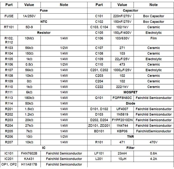
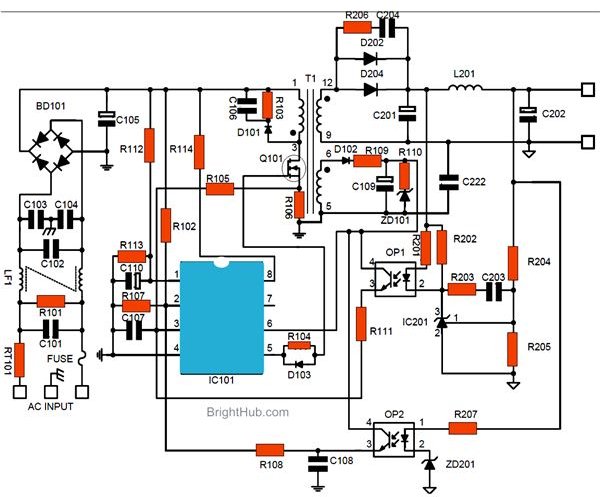
The following diagram shows an ideal switch mode power supply circuit design from FAIRCHILD incorporating the above discussed FAN7602B IC. As it can be seen, most of the components used are all popular types and easily available except the inductor which needs to be constructed at home. The complete construction details of the transformer are also furnished below (from FAIRCHILD application notes). Preferably the circuit may be built over a well designed PCB in order to keep the troubleshooting procedures to the minimum.

Reference
FAIRCHILD Datasheet - FAN7602B


