Ever wondered why only transistors are attributed with the property of current amplification? Basically it’s called the forward current gain or the hFE which is responsible for the amplification factor in transistors. Here, we discuss this in details and also learn how to build a hFE tester.
A Bipolar Junction Transistor (BJT) when operated with DC inputs, the levels of its collector current Ic and base current Ib are related by the term _beta (_β), and expressed as:
β(dc) = Ic/Ib
Practically, transistors may exhibit beta levels anywhere between 50 to 400, depending upon their classification. An increased beta level corresponds to an increased forward current gain of the device, for example a transistor with a beta of 200 may be capable of producing collector currents 200 times more than the applied base current. However, transistors may show considerable difference in their beta levels despite having the same lot and code numbers.
The datasheets showing transistor specifications typically indicate beta as hFE, where the letter h is derived from an equivalent hybrid circuit, while the subscripts F and E are extracted from forward-current amplification and common-emitter configuration respectively.
For alternating potentials beta AC is expressed as:
β(ac) = ∆Ic/∆Ib│V(ce) = constant.
Formally, beta AC is the factor that decides the common-emitter forward–current amplification of the device. This becomes obvious because the collector current is normally the output current for transistors with common-emitter configurations.
Practically, experiments show that the levels of AC current gain β(ac) and DC current gain β(dc) are more or less equal in their magnitudes and therefore become quite interchangeable. Generally the AC and DC betas tend to have similar magnitudes at lower levels of I(ceo).
Importance of the hFE Factor in Practical Circuits
The hFE governs the basic amplification property in transistors and therefore this feature becomes particularly important while designing electronic circuits and selecting the devices appropriately. If we measure the hFEs of a variety of BJTs, we find that as the device becomes bigger in size and capacity, the value of its hFEs starts getting smaller which implies that the devices will be requiring greater base current and voltage for operating their collector loads. The power transistors to be precise come under the low hFE category and the name itself suggests that the power involved with them is always huge, so lower hFEs might be quite justified here.
With smaller BJTs, which are supposed to work with very low power inputs, the hFE plays an important role and higher values become imperative. For example, a transistor may be required to drive a relay of 30ma with a base current of 0.15mA and voltages as low as 1 volts – definitely nothing less than 200 would work here as the hFE.
Let’s say if the Ic is 35mA and Ib is 0.15mA, then the required minimum hFE level would be:
β = 35/0.15 = 233.
Making a hFE Tester Circuit
All modern digital multimeters are equipped with hFE measuring facility. The meters usually have a series of tiny sockets or notches marked appropriately with the transistor lead designations (EBC). Here, the relevant transistor leads just needs to be inserted into the notches to get a direct reading of their hFEs.
Alternatively, a nice little circuit using discrete components can also be built for measuring the β or forward current gain of transistors. Let’s discuss this interesting circuit of a simple hFE tester:
The design is very simple and provides instant indication of the measured hFE through a pot and LED arrangement.
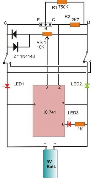
In the diagram, the base current of the transistor under test can be given as:
Voltage across CD – Voltage across BE / R1 - implies that the potential drop across R2 must be = hFE × I(B) × R2.
This allows the settings made by pot VR1 directly proportional to the hFE of the transistor fixed over the points CBE.
The ganged DPDT switch is used to select the NPN or PNP type of transistor, LED1 and LED2 provides with the relevant indications.
Moving the knob of VR1 just illuminates LED3 (for NPN) or just dims it (for PNP) at particular positions, for different transistors. The positions may be appropriately calibrated over a neatly placed dial behind the knob of VR1 for acquiring direct readings of the measured hFEs.
References
Book: Electronic Devices and Circuit Theory By Robert L. Boylestad and Louis Nashelsky.
Bipolar Junction Basics - kennethkuhn.com


