The article provides some easy clues regarding conducting house electrical wiring. A few important tips if followed correctly can make the procedures really simple and without complexities.
Basic Concepts of Household Wiring
Wiring up a house electrically can become really easy once we learn few of the fundamental points involved with it. The following simple tips may be memorized by anybody in the field and applied during wiring-up not only small houses but also large houses or apartments:
-
There are basically four components involved in the whole procedure viz.: Power (Mains voltage), load, conductor, and the switch.
-
Normally our domestic mains power includes two paths, the incoming Phase and the outgoing or the return path through the Neutral. Other than these two the third conduction path in an electrical wiring is the “earth” or the ground.
-
Although not required with fixed appliances like lights and fans, this terminal becomes particularly imperative with the AC outlets or the wall sockets. The top pin in a wall socket is where the earth connection is given. The “earthing” is like a huge electrical dumping ground where stray or residual current leakages are absorbed and nullified.
-
The bodies of potentially dangerous appliances like electric irons, geysers, refrigerators, and soldering irons tend to produce electric shock over time on their bodies due to some portion of the phase leakage. Therefore these appliances have their bodies connected to their plug’s “earthing” pin which ultimately gets configured with the socket’s earthing terminal once plugged in. It becomes very important that the earthing or grounding connection of every house has optimal absorbing capacity for enabling proper absorption of these appliance body current leakages. If in doubt, consult a qualified electrician and get the main ground source corrected.
-
The path or passage of power from phase to neutral is implemented using conductors or wires and the system constitutes an electrical circuit.
-
However, connecting the phase to neutral directly will cause havoc in the form of a big short circuit and the melting of wires.
-
Therefore the right procedure is to connect a load in between these two polarities so that the power flows through the load and operates it, which actually becomes the sole intended purpose of the wiring.
-
But the above procedure will keep the load switched ON permanently, which can become quite undesirable and therefore the introduction of a manually operated circuit breaking or switching device becomes imperative. For this we just need to connect a mechanical switch in line or in series with the load and the phase- that simply solves the issue.
Now let’s see a few simple typical easy house wiring layout diagrams and study them closely.
How to do House Wiring
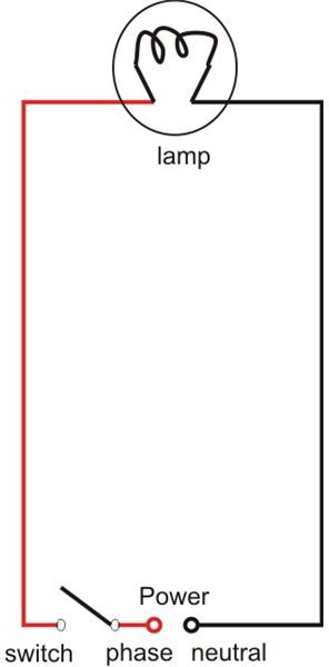
Wiring a Lamp and a Switch: The diagram shows a very simple configuration which can be used for powering a lamp, and the switching arrangement is also provided in the form of a switch. This provides the basic connecting data and the same may be used for wiring up other electrical appliances also (for example a fan).
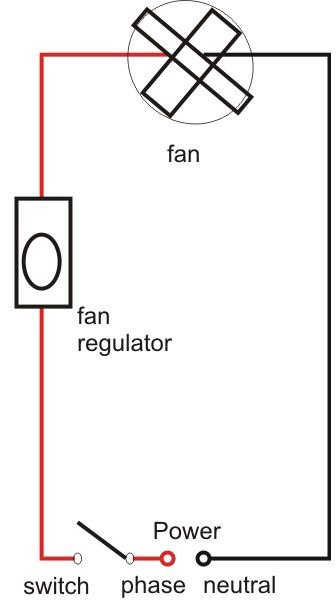
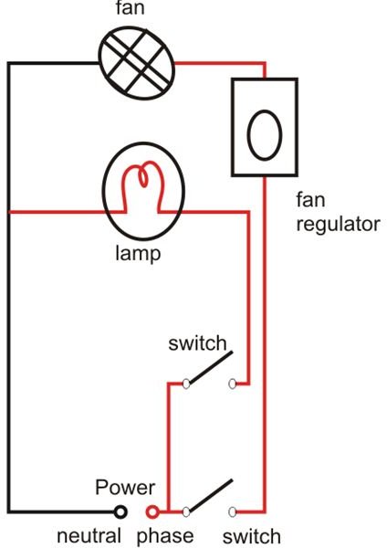
Wiring a Lamp and a Fan in Parallel: Again the configuration employed is similar to the above and is just repeated for the fan. The input phase and the return path neutral are common for both the electrical gadgets or rather for all appliances that may be further included. Note that the fan speed regulator is also a load (mostly resistive) which should be connected in series with the fan and the switch. By adjusting the regulator knob we actually resist the flow of current into the fan thereby checking or varying its speed as desired.
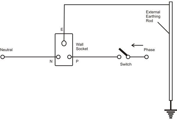
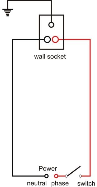
Wiring up a Plug Socket: The wiring is no different from the above ones. Here the load points are just replaced with the socket terminals, or in simple words it’s an outlet for receiving the phase and the neutral potentials through a series switch placed in line with the phase.
Wiring up Heavier Loads: External loads like irons (presses), geysers, mixers, etc. normally have a plug and requires a socket to be plugged into, so sockets wired in the above manner can be used for powering these loads. However the socket/switch assembly and the wires used must all be appropriately rated. The recommended standards are a 3/18 (3 strands of 18 SWG each) for wires and 15 Amps for switch/socket. For smaller loads the specifications may be reduced to 1/18 and 5 Amps respectively.
Please note that although the above electrical house wiring layouts may look easy, there are a couple of things that needs to be taken care of. Firstly, for all configurations the switch must always come in line with the phase and before the load. Secondly the socket’s right side outlet should provide (or be connected) with the phase which again comes only after passing through the switch. Lastly but not the least, every house wiring system should incorporate a sound earthing line for providing the user total safety from residual or leaking body currents from a particular appliance.
The above argument can be understood through the following straight line diagram, see carefully the current path, after commencing from the phase source, it enters the switch, then the load and completes the cycle by ultimately getting back to the neutral point. The third path (earth) though inactive during most occasions, sometimes becomes an important parameter with old and over-used appliances for grounding any residual currents that may be leaking out from the bodies of these appliances.