The proposed design of a 250 to 5000 watts PWM DC/AC 220V power inverter presented here is probably the most straightforward inverter design one can ever get, yet incorporates discrete PWM control features which enables the output square wave to be modified into some optimized waveforms.
I have already discussed quite a few interesting inverter circuits here in Bright Hub, each being unique by its own merits. The present 250 to 5000 watts pwm dc/ac 220v power inverter design is also very special as it uses an unconventional way of creating the required PWM pulses. The power, as mentioned will depend on the output devices and the transformer used, which is off course not a big deal; however we are more interested in the section which generates the PWM pulses using the versatile IC 4060 . Let’s try to understand the functioning details of the present inverter idea.
Circuit Description
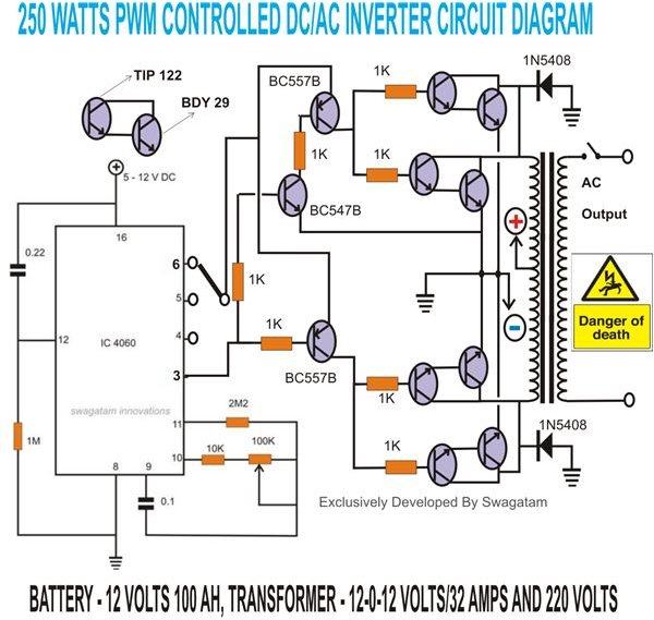
The figure at the left shows the entire configuration of the proposed idea. The inverter stage is a standard push pull type circuit comprising a couple of Darlington paired transistors connected to each half of the transformer winding. The center tap of the transformer goes to the positive of the battery while the emitters of the transistors are connected to their normal places, i.e. the negative of the battery.
Normally the above section just needs the transistors at the two arms of the transformer to be triggered alternately at a particular given frequency. The alternate conduction of the transistor instantly pulls the associated windings of the transformer at full battery potential and the two windings start oscillating, switching the battery voltages alternately through the windings. This develops a huge induced voltage at the output of the transformer providing the required AC power at the output.
However the received power is an ordinary square wave, without any control whatsoever. This output, though, can be used for powering resistive loads, but can definitely become very undesirable for operating sophisticated equipment like TVs, music players, ACs, computers, etc.
The above raw power can however be “tamed” and optimized through a simple PWM design using the IC 4060. We all know that this outstanding tiny chip is able to provide a heck of a lot of different application opportunities and it’s just a matter of configuring it according to the needs. Basically the IC has a built in oscillator circuit which becomes operational by adding a few external components. The oscillating outputs can be obtained through ten discrete pin outs, each having a frequency that’s twice in value to the preceding pin out.
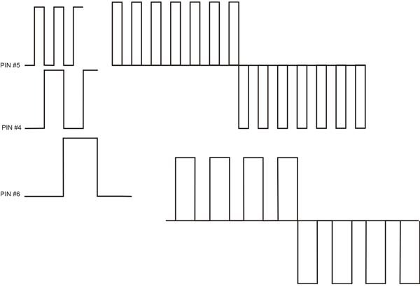
The figure below shows the typical sets of waveforms normally generated by a 4060 IC, and also the derived PWMs for the present 250 to 5000 watts pwm dc/ac 220v power inverter design. As can be seen, every subsequent order of the pin out generates pulses that’s exactly the double in frequency to that of the previous pin out. This varied output range of frequency from this IC ideally suits the present purpose of acquiring PWM pulses- or simply the freedom of dividing each generated square wave into equal discrete divisions. These divisions ultimately help us in optimizing the square waves from the IC into a modified square wave (or sine wave, as some may say), one of the strict criterion associated with quality inverters.
Moving back to the main concept and looking at the diagram, pin #3 of the IC produces the slowest frequency among all the outputs and has been selected for obtaining the fundamental 100 Hz frequency for driving the sets of transistor and constituting the basic inverter operation of converting DC power into AC power. The adjustment is done by setting the 100K pot provided with the IC.
However the main driving voltage is fed to the respective transistors from the pin nos. 4, 5, and 6, which are basically positioned for generating the PWM pulses. This breaks each input 50 Hz frequency wave into a number of discrete sections depending upon the pin out selected. For example pin no. 5 provides the maximum no. of divisions and pin #6 the least no. of divisions among the three options. You may well try the other options also for determining further optimizations.
The output from this modified square wave inverter design is quite at par and can be compared with its more sophisticated counterparts - the sine wave inverters- but the design discussed here is much efficient due to its simple configurations, ordinary components, and an overall easily understandable concept.


