This little home communications system can be used to talk across different rooms or locations within a large premise or an apartment. Build your own following these instructions and circuit schematic.
A very simple, yet highly efficient circuit design, for a home intercom system is covered under this article. The system once built can be effectively used to communicate discretely across ten rooms in a house or an apartment with just a press of a button. The system incorporates a single button selector switch, rather than the usual cumbersome multi switch keypad for the required change over to different rooms.
Let’s straight away move into its working details explained in the following section.
Circuit Description for a Simple Intercom
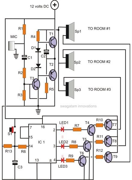
Referring to the figure alongside we see that, basically the circuit is comprised of two stages, viz. the voice or the speech amplifier and the output switching stage.
The voice amplifier stage is a simple transistor coupled high-gain amplifier, consisting of a prior preamplifier and a coupled push-pull amplifier section.
The mic converts the voice signals into small electrical vibrations which are applied to the base of T1.
Transistor T1 which is rigged into a common emitter mode amplifies the above signals, which become available at its collector arm.
The above conductions of T1 causes a current to fluctuate from the positive supply point, through the speaker, via D1, D2 and R4, the latter becomes the collector load of T1 and converts the current amplification into a voltage amplification.
The above voltage amplification is fed to the next push-pull amplifier stage consisting of T1 and T2, which perfectly complement each other and convert the received pulses into high power audio signals. These signals directly drive the connected loud speaker at the output to reproduce the input speeches from the mic. crystal clear.
As the name indicates the above stage works in a push and pull manner. T1 which is an NPN transistor conducts only during the positive peaks of the input oscillations while T2 conducts just in the opposite way i.e. during the negative peaks of the input signals constituting a perfect push-pull effect, resulting in a powerful and distinct audio output.
Solitary this stage can be used as a PA system for amplifying voice signals to a large audience, however since we are interested in a home intercom system, here we would want it to be integrated with another stage through which the voice signals may be transferred to different locations discretely.
An ideal configuration for executing the above function is introduced using the versatile 4017 IC, which effectively switches the output from the amplifier to different locations (one at a time) or a single particular location, as desired by the speaker.
Switch S1 is used as a selector switch for selecting a particular wired location where the voice signals needs to be sent.
Pin #14 is the clock input, which receives the required clock pulses through alternate switching of S1, the output shifts in response to these inputs so that the output of the IC advances in the order of 3-2-4 and back to repeat the cycle.
The relevant LED indicates which output is selected and therefore about the location that’s been linked up with the mic.
The illuminated LED switches the connected transistor pair which in turn connects and drives the loudspeaker located in a particular room, where ultimately the speech information reaches the desired occupant.
It is important to note that each room which are integrated together for the required communications will need to have their own sets of the above equipment so that conservation from both sides becomes feasible.
Parts List
All resistors are 1/4 watt, 5%, CFR unless otherwise stated.
R1, R13 = 10K,
R2, R4, R7, R8, R9, R10, R11, R12 = 2K2,
R5 = 150K,
R3 = 22K,
R6 = 100K,
C1, C3 = 1µF/25V,
C2 = 220µF/25V,
T3, T4, T5, T6 = BC 547B,
T2, T7, T8, T9 = TIP32,
T1 = TIP31,
D1, D2 = IN4148,
IC1 = 4017
MIC = ELECTRET CONDENSOR MIC,
SPEAKERS = 8 OHM, ½ WATT,
LED = RED 5mm.
S1 = PUSH-TO-ON, MINIATURE.


