When it comes to developing your own electronic projects, a prior knowledge of basic circuit theory becomes quite imperative. Read on to learn the bare essentials required for designing your own basic electronic circuits.
What is Basic Electronic Circuit Theory?
In simple terms, electronics may be understood as a branch of science that utilizes and controls the flow of electrons through specially designed networks of active and passive devices to produce a desired result. These networks are basically an interconnection of selected electronic components and constitute an electronic circuit. The electronic components involved are fundamentally classified as active and passive components. Active components play a live role in dimensioning or optimizing the flow of electrons through them as per their design specifications. These are all particularly semiconductor parts which include devices like LEDs, diodes, transistors, ICs, SCRs, triacs and many more, the list may be too long. The passive components are normally made up of carbon or chemical electrolytes and although not able to contribute actively yet play an important part in association with the active devices and complement them in every respect. Without these components, it probably won’t be feasible to design an electronic circuit. Components like resistors, capacitors, inductors etc. come under the passive electronic components.
In this article we will try to learn regarding the basic circuit theory of electronics. We will try to understand the functioning of a few electronic components and also how they may be configured into small basic circuits.
How to Understand the Basic Electronic Components and Their Applications?
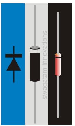
Diode: As shown in the picture a diode is a two terminal component and is recognized by a band or a ring at one of its ends.
In the symbol the band is indicated by a straight line at the arrow point. The lead which is terminating from this side is the cathode and the other one is the anode.
A diode will always allow a positive voltage to pass through its anode towards the cathode and block the other way round. Due to this particular characteristic, diodes are also used as rectifiers to convert AC into DC.
LED: LEDs are quite similar to the normal diodes as explained above, but since LEDs are able to emit light in the process, are specifically used as indicators and in other forms of lighting purposes. LEDs are unable to tolerate high currents and therefore always incorporate a series resistor to dimension the required minimum current through them.
Transistor: We all are quite familiar to this versatile member of the electronic family. Transistors are basically used to amplify small electrical signals and also for switching purposes.
Resistor: Since most semiconductor devices are sensitive to high currents, resistors are employed to restrict a correct flow of current through them. The values of these resistors are dimensioned by calculating them using various formulas.
The following examples will clearly explain regarding how basic electronic circuits are designed:
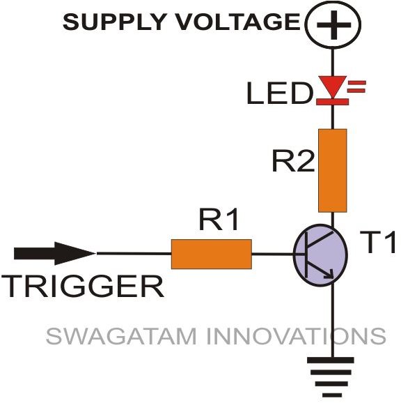
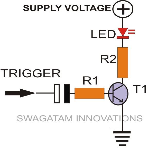
As shown in the figure, the trigger voltage which is generally received from an IC output or some other similar source is applied to R1. The received current is correctly optimized through R1 and is used to bias the transistor T1 so that it may conduct and light up the LED connected to its collector arm.
As explained above, resistor R2 has been incorporated to safeguard the LED from excessive currents. The value of R2 is calculated using the following formula:
R2 = (US - ULED) ÷ ILED
Here US = Supply Voltage,
ULED = Minimum forward voltage drop of the LED used,
And ILED = Current utilized by the LED for optimum brightness (normally 10 mA is found to be quite sufficient).
The value of R1 may be achieved using the following formula:
R1= (Ub - 0.6) × Hfe / ILOAD
Here Ub = source voltage to R1,
Hfe = Forward current gain of T1 used (you may take the minimum value: 150)
ILOAD = Current required to operate the collector load (a LED here).
The LED in the circuit may be easily replaced by a relay, in case it becomes necessary to switch heavy loads at the output. The base resistor value then may also be calculated appropriately using the above formula.
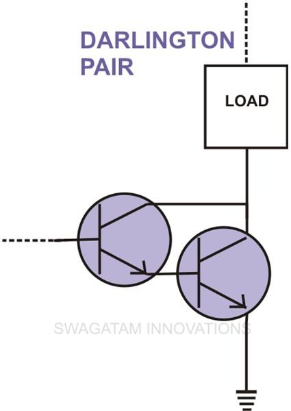
Sometimes we may find the source voltage to R1 too small and difficult for T1 to sense. During such conditions an interesting modification can be introduced by conjugating another transistor with T1 as shown in the adjoining figure. This configuration is termed as a Darlington pair.
Here the received weak signals are amplified to a suitable level by the first transistor and applied to the base of the next transistor which amplifies it sufficiently to energize the collector load.
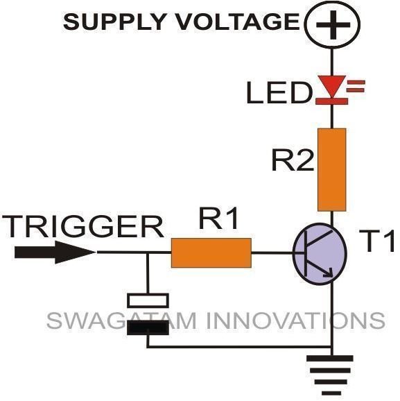
Capacitor: It is another indispensable passive electronic component and inevitably finds a place in almost all electronic circuits. They are basically used to block DC and allow AC but may also find important applications in producing time delays, suppressing or filtering noise..
If a capacitor is linked with the above circuit, interesting results are obtained. The two adjoining figures may be explained respectively as follows:
In the first fig. T1 continues to conduct for quite some time even after the trigger voltage is cut OFF due to the charge stored inside C1, indicating how a capacitor is used in producing time delays.
The second circuit indicates how a capacitor can be used to produce a momentary pulse so that on receiving a base voltage the transistor and its collector load is switched ON only for an instant and then switched OFF. Here the trigger signal is allowed to pass instantaneously only during the charging process of C1 and inhibits its flow once C1 gets fully charged.
Well, I can just go on and on without ending as the topic of electronic basic circuit theory can be infinitely long. But for the time being, I will have to conclude here. Any raised eyebrows? Please let me know through your comments (comments need moderation, may take time to appear).


