This article deals with the construction and working of a single phase ac induction motor. How to make the single phase induction motor self-starting and various methods of self-starting the single phase induction motor are also discussed.
Introduction
In our day-to-day life, we come across many electrical devices like pumps, fans, blowers, etc. All this equipment needs a prime mover, which is an electric motor. In this article we are going to discuss how an electric motor works (single phase and three phase induction motor). An electric motor may be either AC (alternating current) or DC (direct current), but the AC motors have more applications as compared to the DC motors.
What is an Electric Motor?
An electrical motor is a machine that converts electric power supplied to it into the mechanical work of rotating a motor shaft. This is accomplished by the interaction of the magnetic field produced and the current carrying conductor or windings. The electric power supplied may be single phase or three phase.
Construction and Working of Electric Motor
The following data describes the various parts of an electric motor and explains how an electric motor works:
Before going into the working of the induction motor it is very important to know the constructional details of the electric motor. In general the electric motor has two important components. They are
-
Stator
-
Rotor
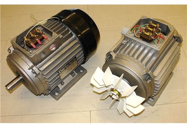
The stator of the induction motor has a solid laminated steel magnetic core. These laminated cores have slots in the inner surface. The phase windings are placed in the slots of the magnetic core and are separately insulated by placing the insulation sheets or dipping it in tank full of varnish and heating it. The ends of the phase windings are taken out to the terminal box. The terminal box has the incoming wire from the three phase supply.
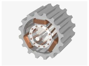
The rotor of the induction motor consists of the laminated core which is mounted on the shaft. This laminated core have slots it the periphery where the conductor bars are placed. It is to be noted that slots are only for the conductor bars and not for the windings. This conductor bars are usually made of copper or aluminum. This bars are short circuited at their ends by the short circuiting ring.
When an AC voltage (single phase or three phase) is applied across the stator winding of the induction motor, current flows through the stator winding and produce a magnetic flux.
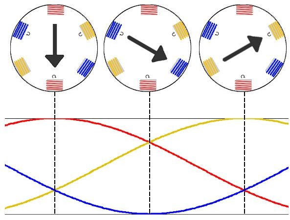
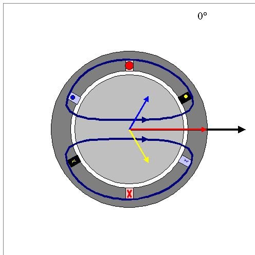
In case of three phase induction motor, the magnetic flux produced is a rotating magnetic flux. This rotating flux will rotate at the synchronous speed which will depend up on the number of poles and frequency of supply given to the motor.
synchronous speed Ns = (120 f ) / p
where
- f is the frequency of the supply.
- p is the number of poles.
This stator rotating magnetic flux cuts through the rotor conductor and induce an alternating EMF. The EMF induced will set up the current to flow through the rotor conductor and produce the magnetic flux. As a result there are two fluxes created (one is the rotating stator flux and the other is the rotor flux). The interaction between these two magnetic fluxes will produce a torque on the rotor, and the rotor rotates in the direction of the rotating magnetic flux. It is to be noted that the rate of cutting flux is directly proportional to the speed of the rotor.
Torque on rotor = Φ × IR × cosφ
where
- Φ is the stator flux.
- IR is the rotor current.
- φ is the phase difference between the stator flux and rotor current.
In the case of a single phase induction motor, the flux produced due to the single phase voltage is only the alternating flux. The alternating flux acting on the stationary rotor (may be a slip ring or squirrel cage rotor) cannot produce rotation on the rotor, and hence the single phase induction motor is not a self-starting motor whereas the three phase induction motor is self-starting motor. To overcome this drawback of the single phase induction motor and makes the motor self staring, the stator of a single phase motor is provided with two windings taking supply from the same phase.
-
Starting winding
-
Main winding or running winding
These two windings are placed 90 degree electrically apart and are connected in parallel to the supply voltage. The current flow through these windings are varied by some means so that the magnitude of flux produced in the stator windings and running windings are different and hence there is some phase difference between these two magnetic flux.
This phase difference creates torque on the rotor for starting. Once the motor is started and attains the rated speed, the supply voltage to the starting windings can be stopped by using a centrifugal switch. As discussed above the current through the two windings are varied by having a high resistance starting winding and a low resistance running winding, or by connecting a capacitor in series with the starting winding.
The images shown below clearly illustrate the parts of an electric motor and relate how an electric motor works.
Three Phase Induction Motor and its Rotating Magnetic Field
Single Phase Induction Motor
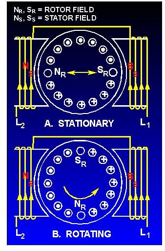
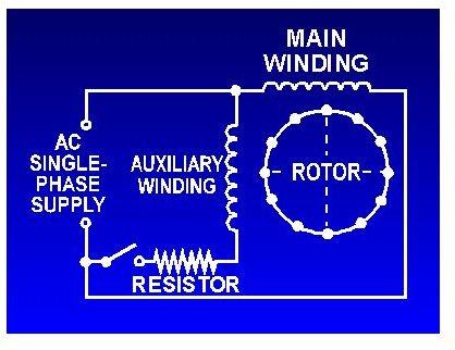
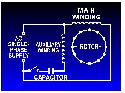
Image Credits
https://en.wikipedia.org/wiki/Induction_motor


