Quick Take
Since it isn’t feasible to produce an ideal Op Amp, certain parameters have to be taken care of for their proper functioning.
On this page
Introduction
Continuing from where we left in the previous article regarding the basic parameters in an Op Amp design, we will now study few more important parameters of an Op Amp IC. They are as follows:
Important Parameters of Op Amp:
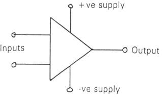
Supply Voltage**: Generally Op Amps are operated with dual supplies i.e. the positive and the negative terminals of the IC are connected to the respective polarities, whereas the free ends of its other components may be connected to the '0' potential.
If you check with a multimeter you will find that this ‘0’ point is at negative potential with respect to the positive supply, and positive with respect to the negative supply of the IC. If the IC is to be operated using a single supply then a resistive potential divider has to be employed to bias its non inverting input.
- Differential Input Offset voltage: No matter how efficient and accurate these ICs may be, it is still not feasible to get an ideal Op Amp IC. There may always exist certain internal instabilities, due to which its out put may refuse to show a zero voltage even when its inputs are grounded. This small error voltage may cause the output of the IC to saturate. This voltage is called the differential input offset voltage and can be neutralized using an external circuit.
- Common Mode Rejection Ratio( CMRR ): If two dissimilar signals( common mode signals ) are applied to the two inputs of an op amp, ideally its output should register a zero voltage. As already discussed this never happens and there is always a small signal present at the output, even when common mode signals are introduced at its inputs. The ability of op amps to reject common mode signals is given by the ratio:
CMMR = Op amp gain with differential signals / Op amp gain with common mode signal.
- Transition Frequency: Op amps are basically designed to handle low frequencies. At higher frequencies its gain tends to decrease and ultimately falls to unity at the ’transition frequency’. These ICs are specified with this open loop frequency response for safety reasons.
- Slew Rate : When a differential square wave signal is applied to the inputs of an op amp, its output may swing from positive to negative saturation. The maximum rate of change of this voltage is termed as slew rate and is expressed in volts per micro second.


