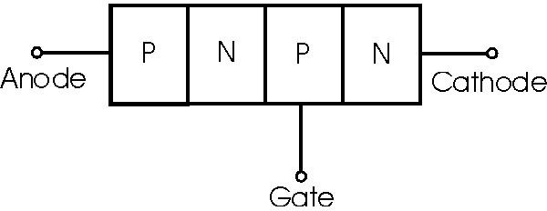
Thyristors are solid-state semiconductor devices with four layers of alternating P and N-type material. In this article we cover the terminology used when dealing with Thyristors, their characteristics, and the basic “controlled rectification” application of SCRs.
If you’ve been reading along and have come here from “Construction and Working of Silicon Controlled Rectifiers ,” you’ll know that they are also called “Thyristors.” Here well look at hows and whys of SCRs, including introducing you to a new world with the several interesting terms used with these devices.
Terminology
Breakover voltage
Also called the forward-breakover voltage, this is the minimum forward voltage with the gate open that the SCR starts conducting. In other words, the point where the SCR is turned ON. For example, if the breakover voltage of an SCR is 100V, then it can block a forward voltage until the supply voltage is < 100V.
Peak Reverse Voltage
This is the maximum reverse voltage that can be applied to an SCR without conducting in the reverse direction.
Holding Current
It is the maximum anode current (with gate being open) at which the SCR is turned off from on condition.
Explanation: As discussed in our previous article , the SCR cannot be turned OFF by removing the Gate voltage. The only way to turn OFF or open the SCR is to reduce the supply voltage to almost zero, at which the internal transistor (refer to the below figure) comes out of saturation and opens the SCR.
**_
Forward Current Rating
It is the maximum anode current that an SCR is capable of passing without destruction.
If an SCr has a forward current rating of 30 A, it means that the SCR can safely carry only 30 A; any attempt to exceed this value will result in SCR’s destruction due to intensive heating at the junctions.
Why is Peak Reverse Voltage Important?
When an SCR is used for rectification, during the negative half cycle of given ac supply, reverse voltage is applied across the SCR. If Peak Reverse Voltage is exceeded, there may be an avalanche breakdown and the SCR will be damaged (unless the external circuit limits the current).
Commercial SCRs have a PRV upto 2.5kV.
V-I Characteristics of SCR
V-I: Curve between anode-cathode voltage(V) and anode current(I) of an SCR at constant Gate current.
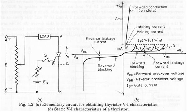
Forward Characteristics (Forward Conduction)
- Anode is +ve w.r.t. cathode
- When supply voltage is increased from zero, suddenly the SCR starts conducting => breakover voltage
- Voltage drops at this point suddenly as shown by the dotted line.
- If proper gate current is made to flow, then SCR can close at smaller supply voltage.
Reverse Characteristics
- Anode is -ve w.r.t. cathode
- Initially the anode current retains small (viz. leakage current)
- Beyond a particular reverse voltage, the SCR starts massive conduction (avalanche) => Reverse breakdown voltage
Controlled Rectification Application
An important application of SCRs is controlled rectification.
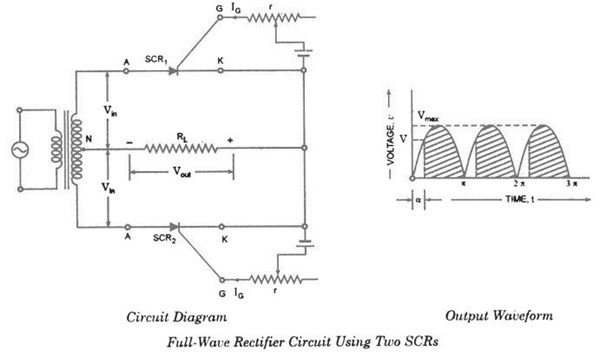
- Two SCRs are connected across the center-tapped secondary, as shown in the above figure.
- The gate signal for both SCRs are supplied from two circuits which control the gate supply.
- One SCR conducts in the positive half cycle and the other SCR conducts in the negative half cycle.
- Thus current through the load will be unidirectional.
- The most important aspect of SCR’s controlled rectification is that the rectification process and hence the output DC voltage can be controlled using the Gate supply control circuits.
The graph shown in the above figure shows the shaded region to be rectified output while the non-shaded part denotes the absence of conduction. This will vary the output voltage.
Firing Angle
The angle (in the input AC) at which the gate is triggered is known as the “firing angle.”
If the supply voltage v = VMAX sin θ and the firing angle is ‘a’ (alpha), then average voltage output will be given by the expression
V****av = V****MAX / ∏ (1 + Cos α)
From the above application, one can infer that SCR can also be used as a switch where the switch can be turned ON by firing the gate and turned OFF by reducing the anode current to less than the holding current.
References
References
Thyristor Defination, https://www.techterms.com/definition/thyristor
Semi-conductor Device, https://www.britannica.com/EBchecked/topic/533976/semiconductor-device/34331/Thyristors
Switching Characteristics of Thyristors during Turn OFF, https://electricalandelectronics.org/2009/04/09/switching-characteristics-of-thyristors-during-turn-off/


