With an ever increasing sophistication in modern music systems, our listening abilities, too, are becoming more and more demanding. A speaker system with perfectly matched crossover networks can be used to produce a hi- fidelity sound output. Read on to learn about three-way speaker crossovers.
Introduction
Some of my previous articles have covered topics like how a tubelight works , building a home made DC mobile charger and so forth. In this article we will learn about the working of crossover network circuit which is used to produce better sound. After reading this you may realize that you have been using this technology for your entertainment for a long time, but did not know how it worked.
Music without sharpness or a voice with no depth is quite boring. No one enjoys listening to a speaker system without a precision clarity in it. Music basically is made up of varying frequencies in the air, for example a guitar or a violin sound may produce frequencies well over 25 Khz whereas drum beats may lie between 100Hz to 500 hz. Human speech is normally in the range of 10- 20 Khz.
To get a hi-fidelity out put from a speaker system it becomes important to have an isolation process of the above frequencies through different channels. Speakers today are designed to handle a particular range of frequency using three-way speaker crossovers.
What is Speaker Crossover Frequency?
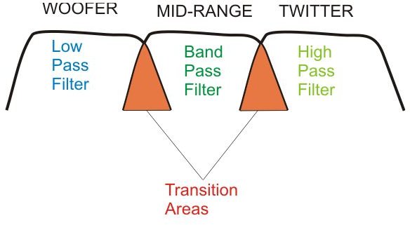
Generally a three way speaker system is able to produce good hi-fi output. It consists of three different types of speakers to handle different frequency contents in a music. The woofer uses the low frequencies, the mid range may handle the speech part and the tweeter is better suited for the highest frequencies in the music. But these speakers wont work properly until the discrete frequencies are fed to each of them. The result is better achieved using a circuit network of inductors and capacitors also called the crossover network.
Here the inherent property of inductors and capacitors are well exploited. An inductor will always try to restrict any rise in frequency passing through it, whereas a capacitor will do just the opposite i.e. higher frequencies will find a better path through them. Thus these components can be properly dimensioned into three types of filters, namely:
- high pass
- low pass
- band pass
for the respective speakers.
No matter how good these 3 way speaker crossovers may be, there always exists an over lapping of these frequencies at a point known as the crossover point. In well calculated crossover networks these crossover transitions are very smooth and the output is distinct with no distortions as may be witnessed through the below given description.
A Practical Circuit Design
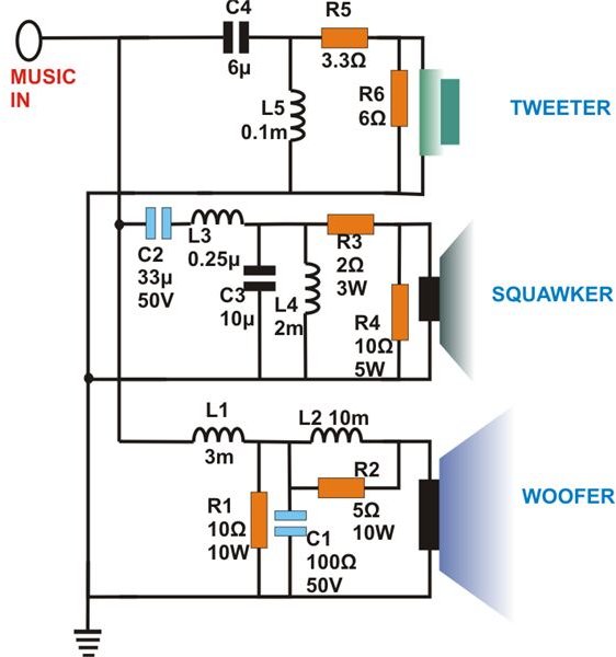
The above explained theory can be better understood through a small circuit design presented here. Readers may go on to build this circuit without hesitation as the idea of this passive crossover filter given below is practically feasible with excellent features. Let’s see how it responds and filters an applied audio frequency:
Referring to the figure, Low range filtration is mainly achieved by inductor L1 and capacitor C1. They result in a good roll over second order slope above 500 Hz.
L2 and C2 are basically responsible for low frequency rectifications.
The inclusion of R1 ensures an overall constant resistance at the network output even with the varying influence of L2/C2 and woofer impedance.
The mid range circuit is comprised of L3-C3 and L4-C2 which help in providing smooth roll offs at frequencies of 500Hz and 5KHz respectively. The roll off curves are at around 14dB per octave.
The tweeter section includes L5-C4 which effectively capture frequencies above 15KHz which is also the cross over point for this section. R5-R6 are arranged as attenuators for level matching at near 6dB to produce an acoustic flat response.
If you are intending to build the circuit, please dimension the wire gauge as per the input power so that the inductors used in the above explained three-way speaker crossovers don’t heat up.
Editor’s Note: Several readers have pointed out that C1 in the diagram should be 100 mH, rather than 100 Ohm, as it is displayed now. You may wish to contact the author of the article about this issue on his blog: https://homemadecircuitsandschematics.blogspot.com/


