A potentiometer is an electrical component with a variable resistance. This article discusses how they work, and how to use a multimeter to read one.
Introduction
In electrical engineering parlance, the term “potentiometer” is used in either one of two ways. It may refer to an instrument that measures an unknown emf or voltage by comparing it to a standard emf. In this capacity, it is functioning as a null instrument; it permits precision measurement by adjusting a value of a circuit element until a meter reads zero. Alternatively, “potentiometer” may refer to an electronic component that is used to vary resistance in a circuit. In this article, we discuss the construction and working principle of the resistive component.
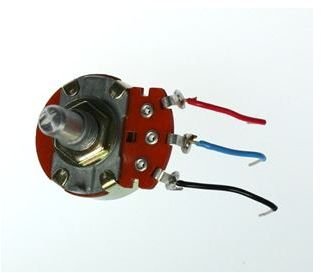
A potentiometer is also referred to as a variable resistor or pot. They have three terminals, where the one in the middle is known as the wiper, and the other two are known as ends. The wiper is a movable contact where resistance is measured with respect to it and either one of the end terminals.
They are useful for circuits where the resistance needs to be dynamically changed to control the current. They are also popular as voltage dividers,
The Basics
Potentiometers come in different types.
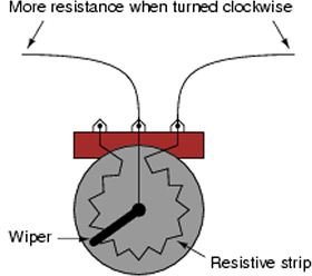
Rotary and trimpot potentiometers are wire wound, and are single or multi-turn, depending on the number of times the knob may be turned. The resistance is lowered or increased by turning the knob clock or counterclockwise, where the knob direction is dependent on the end that is used with the wiper.
Faders or sliders as they are also known, have a rectangular shape, and the wiper moves back and forth in a linear fashion.
How does a potentiometer work?
Potentiometers work by having a resistive element inside. Both end terminals are attached to it, and do not move. The wiper travels along the strip when the knob is turned. The closer the wiper is to the end terminal it is wired in conjunction with, the less the resistance, because the path of the current will be shorter. The further away it moves from the terminal, the greater the resistance will be.
The symbol for a potentiometer is the same one as a resistor, save for an arrow in the middle. In a circuit where they are used strictly as variable resistors or rheostats, only two terminals are wired to the other components. All three terminals are wired separately when they function as voltage dividers. Light dimmers in houses and volume controls on electronics are two common applications. Others include switches and position sensors.
How to Read One
To read a potentiometer, you need a multimeter. Put in on the proper ohmmeter setting, which should be higher than that of the resistance rating of the potentiometer as noted on the package or the device. If you don’t know the resistance rating, use the lowest setting of the multimeter and increase it until you get a reading.
When reading the potentiometer, one multimeter lead must always be on the wiper or middle part, and the other one can be on either of the remaining terminals. For example, place one multimeter lead on the wiper, and the other on the left terminal of the potentiometer. If you place one lead on the left terminal and the other on the right, you will read the entire value of the pot, and the resistance will not vary when you turn the knob.
Note that Inexpensive ones may approximate only fifty percent of their rated value when they are measured.
References
Mims III, F. M. (2003) Getting Started in Electronics. Lincolnwood: Master Publishing Inc
Halliday D., Resnick R., and Krane K (2001) Physics, Volume 2. John Wiley and Sons
Image Credits
Potentiometer by Tony Kuphaldt
Resources
Potentiometers on Northwestern University Mechatronics Design Wiki


