Slip Ring induction motor’s speed can be controlled by injecting e.m.f into its rotor circuit. Read here to know about the Kramer system of injecting e.m.f and Scherbius system for controlling the speed of slip ring motors. Also understand how the cascaded system works.
Introduction:
In my last article we have discussed the speed control of the slip ring induction motors with rheostat and tandem operation techniques. Here we will discuss about the differential cascading and the injecting of e.m.f into the rotor circuit.
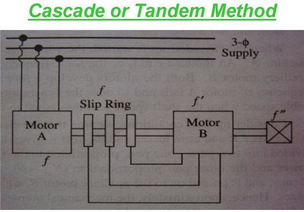
Understanding the Cascaded set
The motor “A” stator is supplied with voltage at a certain frequency. The power available at the stator can be divided and utilized as two parts.
- The power is consumed to overcome I^2 * R and core losses.
- The second part is given to the rotor for its rotation.
The power supplied to the rotor is further consumed into two parts. They are as follows:
- The rotor has to rotate. So, first part is utilized for the rotation of the rotor. “N” is converted into the mechanical power.
- The remaining (Nsa-N) is the power available at slip frequency and this is passed to the slave or auxiliary motor “B.”
Shifting the focus to Slave motor “B” or the auxiliary motor “B”, the power (Nsa-N) supplied to the stator of the motor “B”, is again utilized into two parts.
- To overcome the stator I^2 * R losses and
- Passed to the rotor for its rotation. (Mechanical power).
N — actual speed of the cascaded set.
Nsa — synchronous speed of motor A, being independent of N.
Now when the cascaded set is supplied with the voltage at a frequency to the stator of motor “A”, an e.m.f is induced in the rotor “A” at same frequency. This is supplied to motor “B”, thus both the motors start to develop a forward torque. As the shaft speed increases, the rotor frequency of motor “A” falls thus making the synchronous speed of motor “B” to fall. The cascaded set settles down at a speed which is stable, when the shaft speed equals the speed of rotation of the field of motor “B.”
It can be seen that the mechanical outputs of the two cascaded motor set are in the ratio similar to the ratio N: (Nsa-N).
It is also evident that the mechanical outputs are in the ratio of number of poles of the motors.
Differential Cascading
Let us now discuss on the Differential Cascade Connection:
In this method, the direction of phase rotation of the stator field of motor “B” is in opposite direction with respect to direction of phase rotation of stator field of motor “A.” We already know how to reverse the direction of rotation. It is done by just interchanging any two leads of the stator terminal of motor “B”. The terminals are coming from the slip rings of motor “A.”
As discussed already in my previous article,” speed control of induction motors”, the synchronous speed of the cascaded set can be given by
Nsc = 120f/ (Pa + Pb).
In the same way, the synchronous speed of the differentially cascaded motor can be given by the expression
Nsc = 120f/ (Pa – Pb).
Injecting E.M.F in Rotor Circuit
The e.m.f injected in the rotor circuit must have the same frequency as the slip frequency, by which the speed control of slip ring induction motor is achieved. But there is no restriction for the direction of phase rotation. When the injected voltage is in phase opposition with the induced rotor e.m.f, then the rotor resistance increases. In turn when the injected voltage is in phase with the induced rotor e.m.f, then the rotor resistance decreases. Thus by changing the direction of phase rotation, the resistance of the rotor circuit is varied and thus speed of the slip ring motor is controlled.
Kramer System
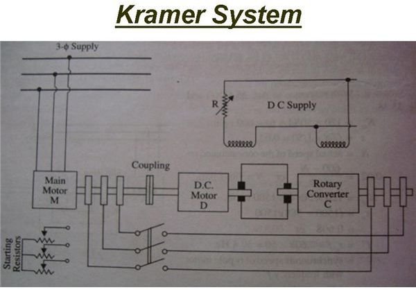
This system is basically used for the speed control of large motors of rating more than 4000Kw or above. The main motor “M”, has slip rings mounted on its shaft from which the e.m.f is supplied to the slip rings of a rotary converter “C.” The rotary converter converts the low-slip frequency a.c. power into d.c. power, which is used to drive a d.c. shunt motor “D”, mechanically coupled to the main motor “M.”
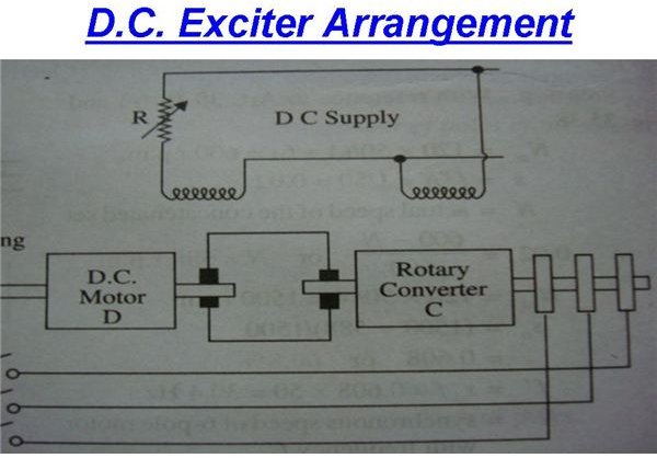
The main motor “M”, is directly coupled with the d.c. shunt motor “D.” The d.c. output oc the rotary converter “C” is used to drive “D.” Both “C” and “D” are excited from a separate d.c exciter or d.c bus bar. The field regulator governs the back e.m.f Eb of “D” and hence the d.c. potential at the commutator of “C” which controls the slip ring voltage and thus the speed of motor “M.”
Advantages:
- Any speed can be attained within the working range of the motor, instead of two or three speeds in other kinds.
- The power factor of the system is improved if the rotary converter is over-excited.
Scherbius System
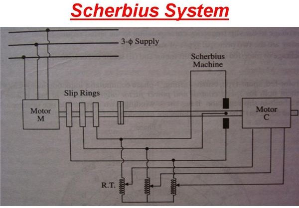
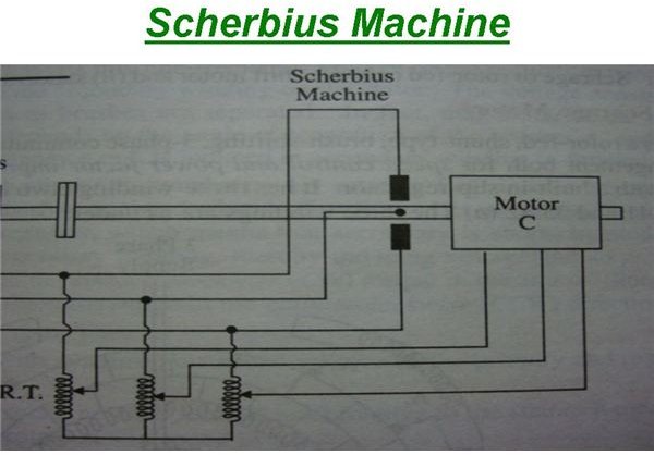
In this system, the slip energy is not converted into d.c and then fed to a d.c. motor. But it is fed directly to a three phase or six phase a.c. commutator motor called as Scherbius machine. The low frequency output of the machine M is fed to the poly phase winding of the machine C through a regulating transformer RT. The commutator motor C is a variable speed motor and is controlled by either the tapping on RT or by adjusting the position of brushes on C.
Reference:
“A Text Book Of Electrical Machines” by Nagoor Kani.
A/C-D/C Machines by Theraja.


