Find out more about EMI (Electromagnetic Inference) and how it effect the performance of electrical systems.
Electrical Faults due to EMI
Introduction to EMI
Current is defined as the flow of electrons. It is produced as result of electrons traveling along a wire or trace. Electrons possess a negative charge. We can say that a negative field is associated with a wire or PCB trace when a current flows through it. The greater the number of electrons, the greater the amount of current causing a field of high intensity.
This negative field along the wire/trace is known as the electric field, and is denoted by the letter E. Similarly a magnetic field is also associated with current flowing through conductor/trace. This field is denoted by the letter B. The magnetic field strength varies just like the electric field with a variation in current. Together these two fields are termed the electromagnetic field (H). Both these components move with a speed almost 2/3 to the speed of light.
According to Faraday and the law of electromagnetic induction, when a magnetic field varies, changes in flux lines are produced. This varying magnetic flux produces a current in the adjacent wire. Our TV and other microwave receivers and transmitters work on this principle, although this is not desirable in some cases. The phenomenon is called EMI (electromagnetic interference) or cross talk.
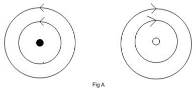
Figure A below (please click to enlarge) demonstrates the magnetic flux along a wire with the current flowing outward. By applying the Right Hand Rule, we can get the direction of the magnetic flux lines, which are anticlockwise. These flux lines cut across the second wire (on the right) and induce an EMF, or electromotive force, in that wire. The magnitude of this induced EMF depends on the coupling coefficient K between the two conductors. The value of K varies from 0 to 1: zero means no induction and one means maximum induction.
According to Lenz’s Law, the induced current will flow inward in conductor B, creating flux lines opposite in direction to conductor A. An observer will see the radiations of one conductor as stronger than the other relative to its distance from conductor. But if we move these conductors close together, then the observer will see the radiation of both conductors as equal in magnitude and opposite in phase, so they cancel each other effect.
From this demonstration we learn that to minimize the effect of EMI in a wire or trace, the return path should be as short as possible. To minimize the effect on return (GND) path, the loop area should be the minimum possible. Loop area is the area followed by current as it flows from the source and returns back to the source. This is easy to say but difficult to implement.
Figures
EMI and GND Path/Return to Ground
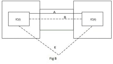
Figure B demonstrates a scenario in which two circuit boards are connected via a connector. The signal flows between IC (i) and IC (ii). Now the question is, what should be the appropriate return (GND) path of this signal? Here we have two cases:
Case1: We can use pin A for return (Ground) and the loop area will be will be small.
Case2: If we use pin E for ground return, the loop area will be greater and EMI will create a problem on return by imposing an EMF. This shifts the ground voltage level up.
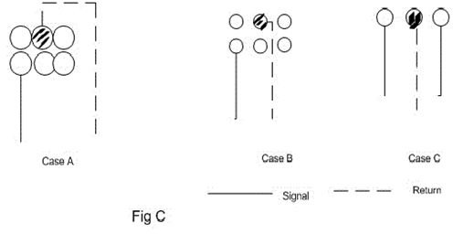
Figure C is showing another common problem of EMI on return (Ground). The figure shows clearance holes for a connector/component pins. Here we have three cases:
Case 1: In this scenario the signal trace is connected to one pin and its return (Ground) on back side. The holes under connector are wide enough to remove all the copper under it. So its return (Ground) is long and EMI will create problem on ground.
Case 2: provides a better solution with small holes; the signal is returned between the holes, creating a small loop area.
Case 3: provides a perfect solution; there will no effects of EMI on return.
GFI Trips due to EMI - What to Do for Them
Similarly EMI can also induce an EMF in a GFI breaker, causing the GFI to wrongly trip because of noise in the power line. To avoid this problem an EMI filter is installed at the input of GFI breaker. A UPS and a surge suppress can also be used. EMI can also get coupled at the output of GFI causing enough noise to trip the GFI. To avoid such problems, the wire length between the GFI and load must be kept at the minimum.
A power conditioner or transformer can also be used to isolate the GFI input and outputs, helping the GFI breaker avoid false tripping.


