Piping and instrumentation diagram (P&ID) is used extensively in process industries. This article will describe the procedure for creating P&ID using AutoCAD.
What is a P&ID?
A piping and instrumentation diagram (P&ID), sometimes called piping flow diagram or process flow diagram, is a kind of schematic drawing, which shows the sequence of process equipments and instrumentations. P&ID is used for erection and commission as well as during maintenance of a process plant.
Basic Rules for Creating P&ID
- Pipe lines are represented by single lines in P&ID.
- Instrumentation signals and connection lines are represented by different types of dashed lines.
- Industry standards for the P&ID are ISA S5.1 and ISO 14617-6.
- P&ID should be readable either from left to right or from right to left of the drawing.
- P&ID is the representation of the process equipment/instruments sequence and not the distances between the equipments/instruments.
How to Draw a P&ID using AutoCAD
Let’s say you want to create a P&ID in AutoCAD for the water distribution system of your house. Proceed as follow:
-
Understand the system correctly. Note down the equipments and instruments connected to the pipelines.
-
Know the symbols of the equipments/instruments from the standards.
-
Draw the blocks of the equipments/instruments in AutoCAD. Place the blocks in sequence.
-
Connect the blocks with line.
-
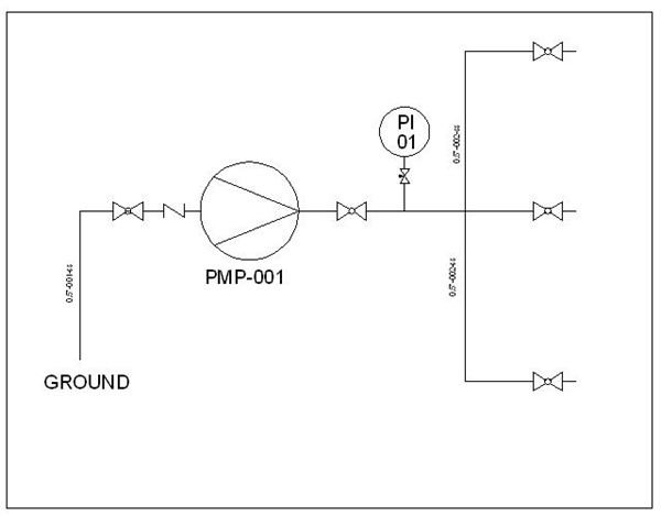
Give name to each line segment. While naming a line segment, you should mention its size, serial number and material of construction. See the water distribution system P&ID below:
-
Each process equipments and instruments need to be given unique name. In the above water distribution system P&ID, the pump is named as PMP-001 and pressure indicator as PI 01.
-
Electrical lines , pneumatic lines and hydraulic lines should be represented by different types of broken lines and to be named.
Conclusion
Complexity of the piping and instrumentation diagram (P&ID) may vary from case to case but all of them follow the same basic rules as we discussed. If you are using standard module of AutoCAD for making P&ID then you have to create the blocks of the different equipment and instrument symbols by your own. Some of the AutoCAD module have inbuilt blocks. You can make use of AutoCAD dynamic blocks for creating the symbols.


