Interested to know about those machines that bottle your favorite beverage? How exactly the whole mechanism rely and follow a custom carved cam? Read on for a detailed knowledge of these smart mechanisms.
Concept and Definition
-
A cam is a rotating machine element which gives reciprocating or oscillating motion to another element known as follower. The cam and follower have a point or line contact constituting a higher pair.
-
The contact between them is maintained by an external force which is generally provided by a spring or sometimes by the weight of the follower itself when it is sufficient.
-
The cam converts rotary motion of one element into reciprocating (linear) motion or into oscillatory motion. The cam is the driver member and the follower is the driven member.
The cam and follower mechanism is widely used for operating the inlet and exhaust valves of internal combustion engines. They are used in wall clocks and the feed mechanism of automatic lathe machines. They are also used in paper cutting machines and weaving textile machinery.
Image Credit: en.wikipedia.org
Classification of Cams
Cams may be classified in many ways. The most important classification is based on the motion and displacement of the follower with respect to the axis of rotation or oscillation of the cams. Based on this, the types of cams are as follows:
-
Radial or Disc Cam: In the radial cams, the working surface of the cam is designed such that follower moves in a plane perpendicular to the axis of the cam performing a reciprocating or oscillating motion.
-
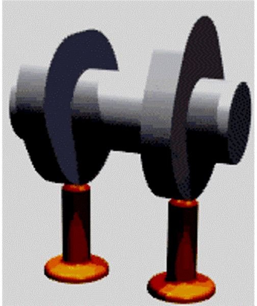
Cylindrical Cam: In this type of cam, the follower either reciprocates or oscillates in a plane parallel to the axis of the cam. In this a circumferential contour is cut in the surface of the cylinder which rotates about its own axis. The follower rides in the groove of the cylinder surface and it reciprocates in the plane parallel to the axis of rotation.
-
Wedge Cam: Here the cam has translatory motion and the profile of the cam is formed on one side of the cam.
Classification of Cam Followers
According to the Surface Contact:
-
Knife edged followers: These are simple in construction. The contacting end of the follower with the cam has a sharp knife edged hence it is called so. The motion between the cam and follower is sliding. It is not used in practice because small area of contact surface results in high rate of wear at the edges due to which the transmission of motion may not be accurate as desired.
-
Roller follower: The contact end of the follower is roller and the rolling motion exists between the cam and follower. Compared to knife edge followers, the rate of wear and tear is less due to less friction. These are used in aircraft engines and oil engines.
-
Flat face or mushroom follower: These are used where space is limited to operate valve of automobile engine. The contact surface is perfectly flat. The side thrust between guide and follower is much reduced. It is called a mushroom follower when the flat face is circular.
-
Spherical follower: When the contact end of the follower is of spherical shape.
According to the Path of the Motion of the Follower:
-
Radial follower: In a radial follower the follower translates along an axis passing through the center of the cam.
-
Offset follower: The axis movement of the follower is away from the axis of the centre of rotation of the cam.
Sources :
Cam and Follower Design Basics


