Various compression spring calculations are required now and then by engineers. This article covers five types of important helical compression spring calculations and a typical example is discussed.
Various equations are used for calculating the different parameters related to the compression spring. We will not go in details of derivations of the equations rather limit our discussions to the applications of the equations to the different compression spring calculations.
1. Shear stress calculation for the circular wire helical compression spring: The maximum shear stress for a circular wire helical compression spring is given by:
Smax = (8KWC)/(Πd2) ………………eqn.1
Where,
Smax is maximum shear stress to the spring wire
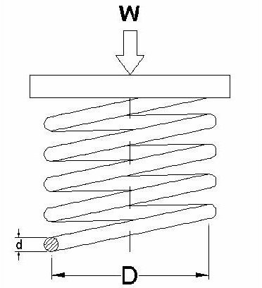
D is the spring coil mean diameter
d is the diameter of spring wire
W is the applied load
C = D/d
K= Wahl’s factor = [(4C – 1)/(4C – 4)] + (0.615/C)
2. Axial deflection calculation for circular wire helical compression spring: Under applied load, the spring got deflected. The axial deflection of the compression spring can be determined by:
X = (8WC 3 n) / (Gd)………………..eqn.2
Where,
X is the axial deflection due to the load
W is load
n is the active coil number
G is modulus of rigidity
3.Maximum twisting moment calculation: The maximum twisting moment (T) of the helical compression spring can be calculated by the following equation:
T = (Π Smax d3 )/16………………eqn.3
4. Buckling calculation for a compression spring: The minimum axial force, which is required to buckle an axial spring can be obtained from:
Wb = Kb k Lf ………………eqn.4
Where,
Kb is the buckling factor (values available in any design data book)
k is spring rate
Lf is free length of the spring
The basic concept to remember here in buckling is: as long as the spring free length (Lf ) is less than four times the mean diameter of the spring, your spring is safe from buckling.
5. Calculation of free length (Lf ) of the spring : The free length of the spring can be calculated by:
Lf = n’d + 1.15X………………eqn.5
Where,
n’= total number of coils of the spring.
Example
So, by now you must know all the useful compression spring calculations and equations, But how to use them practically? Well, the practical design example I am going to discuss here, will give you an idea regarding that.
Problem: Find out the mean diameter (D), the wire diameter (d), the number of active coils (n) and the free length (Lf ) of the spring against the following given data:
Preload on the spring (W1) = 250 N
Final load on the spring (W2) = 400 N
Initial Deflection due to preload (X1) = 50 mm
Final deflection of the spring (X2) = 60 mm
Maximum permissible shear stress (Smax) = 400 MPa
Modulus of rigidity (G) = 80 x 103 MPa
Inside diameter of the spring = 25mm
Solution:
- Finding the mean diameter (D) of the spring and the spring wire diameter(d):
The mean diameter of the spring (D) = inside diameter of spring + diameter of the spring wire = 25 + d
By using the eqn.3 we got:
T = (Π Smax d3 )/16
Or, 400(25+d)/2 = (Π Smax d3 )/16
Or, 200(25+d) = (Π * 400 * d3 )/16
Or, d = 4.2 mm
So, the spring index C = D/d = (25+d)/d = 6.6
And, the value of K = 1.227
Now, you have to use this C value in eqn.1:
400 = (8 * 1.227 * 400 * 6.6)/ (3.14* d2 )
Or, d = 4.54 mm
Among the two values of d, we will take the greater one i.e. 4.54 mm and from standard wire size table we find that next standard size wire has diameter = 4.877 mm.
So, final wire diameter is 4.877 mm.
So**, the mean diameter of the spring (D)** = (25+d) = (25+4.877) = 29.877 mm
- Calculations of the number of active coil : The number of active coils can be calculated from the eqn.2 like below:
X = (8WC 3 n) / (Gd)
Or,(X2 - X1 ) = {8*(W2 -W1 )* C 3*n}/(Gd)
Or, 60-50 = {8*(400-250)*6.63 *n}/(80000*4.877)
Or, n = 14.2 , the nearest full number is 15.
So the numbers of active coils are 15.
Assuming the squared and grounded ends, the total numbers of the coils (n‘) are 15+2 = 17.
- Calculation of free length of the spring (Lf): Use the eqn.5 to find out the free length as below:
Lf = 17*4.877 + 1.15*X
X is the maximum deflection of the spring. As the spring is getting deflected by 10 mm with 150 N load change, so, the possible deflection under the maximum applied load ( 400 N) = X = (10/150)*400 = 26.67 mm
By using this X value, we obtain the free length of the spring = 113.58 mm
Conclusion
The helical compression spring calculations typically use five spring equations discussed in this article. The compression spring design example discussed above is a typical one to show the approach of solving the helical compression spring related problems. An online compression spring design calculator is also available over the web.


