What is a hemispherical combustion chamber? Is it better than the wedge and flathead designs? Does HEMI give more power than other designs? The basic requirements of a good combustion chamber and the design principles have abandoned a number of configurations historically used. Is HEMI better?
Combustion Chamber
In diesel and gasoline engines the enclosed space where the combustion of the fuel takes place is called the combustion chamber. It is an enclosed volume bound between the cylinder head and the top of the piston. The layout and the shape of the combustion chamber depend on the profile of the piston top, the shape of the cylinder head, the location and the arrangements of the inlet and exhaust valves, and the spark plugs. The design of the combustion chamber influences the performance of the engine and its anti-knock properties. The layout and shape of the combustion chamber has a bearing on the thermal efficiency and performance as well, and thus different types of combustion chambers have been designed and used over the years (and still the research is on). It must be noted that the design of the combustion chamber is different for the spark ignition (gasoline) engines and compression ignition (diesel) engines. In this article we will be concentrating on the design principles of the spark ignition engines.
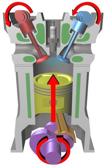
Four Stroke Engine Combustion Chamber
Basic Requirements of a Good Combustion Chamber
The main requirements of spark ignition combustion chamber design are high power output with minimum octane requirement of the fuel, high rate of thermal efficiency, and smooth engine operation at all gears.
For getting a high power output from the same size of the engine, the compression ratio of the engine has to be increased. The compression ratio is limited by the detonation and knocking and depends on the fuel quality and chamber design. The second factor is that no excess air should be used and complete utilization of the air should be made. Needless to say, no dead pockets should remain inside the combustion chamber. The third factor is high volumetric efficiency that is achieved by having large diameter valves along with good timing and straight passageways to allow flow of the gases with the least pressure drop.
For getting a high thermal efficiency, a high compression ratio is. The second factor for thermal efficiency is to have minimal heat loss during combustion, which can be achieved by giving a small surface to volume ratio to the combustion chamber. Turbulence also speeds up the combustion and reduces the combustion time loss, hence allowing the speed of the engine to be increased. The third factor for getting a high thermal efficiency is to have good scavenging of the exhaust gases, because any remaining exhaust gas inside the combustion chamber will lead to the dilution of the charge and loss of efficiency.
For getting smooth engine operation we must have an absence of detonation and a moderate rise of pressure during combustion. These in turn depend basically upon having a compact combustion chamber design which allows for a short distance of flame travel. The second factor is the correct location of the spark plug and the exhaust valve to allow the proper prorogation of the flame front and the exhausting. The third factor is that the cooling of the spark plugs should be done so that the hot spark plug points do not trigger any pre-ignition.
Principle of Combustion Chamber Design
No matter what new innovation the automobile companies claim to have made or any new radical design developed, the principles of combustion chamber design are the same:
- The inlet valve should be as large as possible to achieve a high volumetric efficiency.
- The length the flame has to travel should be as short as possible to avoid detonation of the charge. This would involve the design of the combustion chamber, the location of the spark plugs, and installation of multiple spark plugs to start multiple flame fronts.
- Hot spots that can cause pre-ignition should be avoided by cooling and the location of the spark plug and the exhaust valve. A smaller area of the exhaust valve would offer less chance of hot spots. The small area can be compensated by increasing the lift of the valve.
- An optimum degree of turbulence should be provided so that the velocity of the flame propagation is the highest. This would decrease the combustion time and increase the thermal efficiency.
- Cooling has to be optimum, a high degree of cooling would reduce the thermal efficiency and low cooling could lead to pre-ignition or material failure.
- The surface to volume ratio should be least so that loss of heat is avoided and we can get a high thermal efficiency.
- According to the grade of the fuel used the highest compression ratio should be used to increase the thermal efficiency.
- Scavenging must be efficient to reduce exhaust gas dilution.
These are few of the design principles used by design engineers.
Historic Combustion Chambers
In history a number of different type of combustion chambers were used which were quite popular at that time but were discontinued as better technology was available. We will discuss some of these now.
- T Head Combustion Chamber: This was used in Ford famous model T car. It was however very successful as it had two cam shafts and the prone to detonation even at a low compression ratio of 4:1. In this T head combustion chamber both the inlet and the exhaust valves are located at the opposite types of the combustion chamber. This type of combustion chamber was common as it those days the fuel available was of octane rating about 45 and highly prone to self igniting. A far and isolated exhaust valve lead to fewer self ignitions.
- I Head Combustion Chamber: These were also called Side Valve Combustion Chambers or Flat-heads, and both the inlet and the exhaust valves were placed on side of the engine together. This type of the engine was easier to manufacture and the maintenance was also easy as the complete valve block could be removed for overhaul. However it was prone to detonation as large flame length was large and the air had to take two right turns to reach the combustion space resulting in less turbulence.
- F Head Combustion Chamber: In this type of combustion chamber one valve is located in the side pockets and the other is located in the cylinder head. The F head type engine was better than the T head engine but the valve operating mechanism was a bit complicated.
Contemporary Combustion Chambers
After 1950- 1960’s the overhead valve type of combustion chambers were used. In this type of cylinder head both the exhaust and the inlet valves are placed on the cylinder head and are slightly inclined to the cylinder axis. These types of combustion chamber are characterized by high volumetric efficiency, smooth operation, and a high power output as compared to the other designs. In addition in these type of engines the pumping losses are less, greater anti knock properties as the flame front has to travel less and consequently less octane gasoline is required. The two important types of overhead valve combustion chamber are bath tub combustion chamber and wedge form combustion chamber.
Bath tub type combustion chamber is an oval shaped combustion chamber with the valves mounted overhead and the spark plug at the sides. In this design all the valves are placed in a single line on the cylinder block and thus are easier to manufacture.
In the wedge form of the combustion chamber the valves are inclined at an angle to the axis of the cylinder. In the wedge type of design the actuation of the valve is simplified as they are together, but the air fuel ratio has to make sharp turn to enter in the chamber thus increasing flow resistance and affecting scavenging. But as the combustion space is narrower it leads to shorter flame travel distance and therefore less knocking.
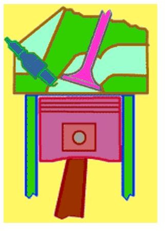
Wedge Shaped and Bath Tub Combustion Chamber

What is a Hemispherical Combustion Chamber
A hemispherical combustion chamber, also known as the HEMI, has a combustion chamber in the shape of a half sphere. The hemispherical combustion chamber has an advantage of cross flow design that allows the engine to breathe better. The hemispherical engines are in use from the early 1900’s and were widely used. The newer style hemispherical combustion chamber is not a true hemisphere but a partial hemisphere. This modification is to give some turbulence to the engine. The hemispherical combustion chamber generates more power as the air does not have to turn at right angles and the resistance to its motion is less. However emission problems are more on a hemispherical combustion chamber and hence the new HEMI are only partially hemispherical. The key advantage of a hemispherical combustion chamber is that its surface area to volume ratio is the least in the category a compared to other designs like flat head, wedge heads, etc. and therefore they have a superior thermal efficiency than other engines. Also, as the valves are located cross-wise, the valves can be made large resulting in better scavenging or breathing of the engine.
HEMI Design
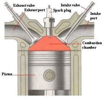
Image Credits
- Four Stroke Engine Combustion Chamber: https://upload.wikimedia.org/wikipedia/commons/f/f7/Four_stroke_cycle_compression.jpg
- Bath Tub Combustion Chamber: https://www.motorera.com/dictionary/pics/b/bathtub_chamber.jpg
- HEMI Design: https://www.motorera.com/dictionary/pics/c/combustion.jpg


