This article deals with Bibby Resilient type couplings. The article describes constructional aspects of the coupling and the selection procedures for the coupling.
Named after its Inventor Dr. James Bibby in 1917, this coupling is still one of the most sought after flexible couplings for heavy shock applications. Let us now look at the constructional features of the coupling.
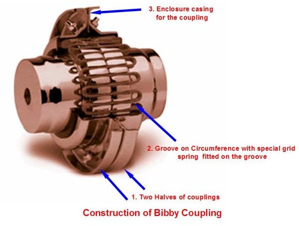
- The Coupling consists of two flanges or hubs specifically mounted on the drive and the driven shafts respectively. These hubs contain axial grooves cut on their circumference.
- The two couplings are joined or held together by means of a specially designed grid spring.
- The total assembly is enclosed in a casing or shell filled with grease for low speed applications or, in high speed application with high viscosity oil.
Now let’s look at the working aspect of the coupling and how it tends to reduce vibration and prevents the build up of resonance in the system.
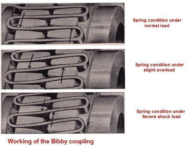
a.) The specially designed spring is wound up through the grooves forming a series of resilient bridges throughout the periphery of the coupling.
b.) The grooves are tapered up at the edges (see photo) in order to provide extra flexible spans to the spring at normal loads and tends to support the spring at the sides whenever overloading occurs.
c.) The stiffness of the spring depends on its unsupported length of each of its flexible span. The unsupported length tends to vary with the loads producing a varying stiffness for the coupling based on the loading.
d.) This action tends to produce a detuning action altering the torsional vibration frequency of the system that prevents the build-up of resonance.
Some applications of Bibby Couplings are
- Cement Mills – in grinding and crushing machinery.
- Cranes
- Conveyors
- Turbines
- Marine Auxiliaries
- Paper Mills
Bibby couplings can be used for applications with powers varying from as low as 1 h.p to about 100,000 h.p. per 100 rpm of the coupling. Correspondingly the couplings are available in varying sizes ranging from 100mm diameter to 4000mm diameter.
Bibby couplings are capable of taking axial and radial misalignments to a very small extent only. It is necessary for the user to ensure that both axial and radial misalignments are kept to the minimum possible.
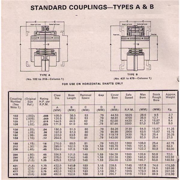
Selection procedure for Bibby Couplings:
The selection of the Bibby coupling is mainly based on the torque being transmitted by the coupling. Each coupling has a characteristic value for the torque transmitted by it to the revolutions per minute of the coupling.
The rating of the coupling is given by
Rating = Maximum power to be transmitted in h.p/ r.p.m of coupling
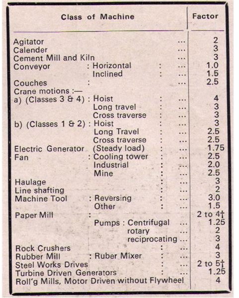
In order to account for contingencies like shocks, sudden stops, stalling, etc. a factor of safety is to be considered during selection of the coupling.
Rating of coupling to be Selected = Max. power of coupling* Factor/ r.p.m. of coupling
The chart containing the factors to be considered is given below based on the application and driving machinery.
See the selection chart below for the selection of corresponding coupling based on the power. Note: This chart is an indicative for the selection of the Bibby coupling. Kindly refer to an actual manufacturer’s catalog for selection as ratings may vary from manufacturer to manufacturer.