Learning hydraulic component symbols is the essential first step toward reading hydraulic schematics. We will discuss glossary of ISO hydraulic symbols here in this article.
There are many hydraulic symbols used in industry for designing and reading hydraulic circuits. Here in this article we will learn five most used ISO hydraulic symbols and their practical meanings:
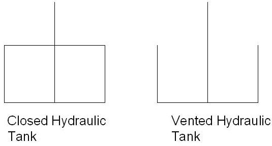
1. Hydraulic Reservoir (tank)
Every hydraulic system must have a storage tank for string hydraulic fluids. This is called the hydraulic reservoir. Hydraulic reservoirs are represented as:
Except in aerospace applications, vented hydraulic tanks are used in most cases. The vertical line touching the bottom line indicates that the line is going below the fluid level.
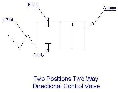
2. Hydraulic Directional Control Valve
The direction of hydraulic fluid flow is controlled by a directional control valve . A directional control valve broadly consists of four parts. Namely, these are the valve body, valve spool, actuator, and spring . The valve spool get shifted with respect to the valve body which opens or closes valve ports for controlling fluid flow. The actuator provides power for shifting the spool and the spring pushes the spool back to its normal position. Look at the representation of a typical two position two way valve:
Tips for reading directional control valve symbol:
-
The number of boxes shown in the valve symbol is the number of positions for the valve. In the above symbol two square boxes are there so it is a two position valve.
-
Number of ports tells how many pipes can be connected to the valve.
-
Actuator always pushes and never pulls the spool.
-
The box, which is away from the actuator, is the neutral or normal position of the valve. This way the above shown valve is normally closed valve.
3. Pressure Relief Valve
In hydraulic systems, pressure is generated by pumps. But if pumps develop more pressure than the system design pressure, then it may spoil the hydraulic system itself. Pressure relief valve protect the system for such cases. A pressure relief valve is typically represented as:
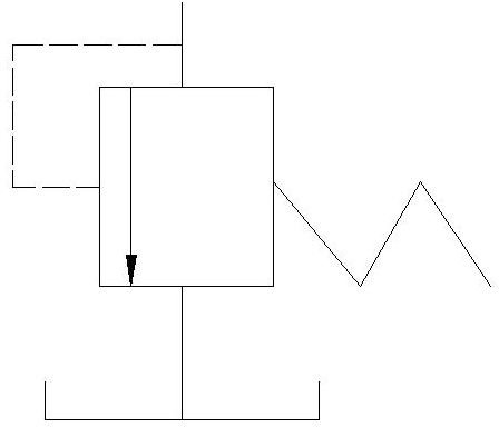
In a case when a pressure relief valve or PRV is activated, the fluid goes to tank. Fluid pressure in the dotted line acts as actuator for the PRV. If fluid pressure increase beyond a specified value (decided by the spring) the PRV gets activated and fluid releases to hydraulic tank until the pressure come back to normal.
4. Hydraulic Cylinder
Hydraulic cylinder converts hydraulic power to mechanical power or vice versa. A hydraulic cylinder is typically represented as:
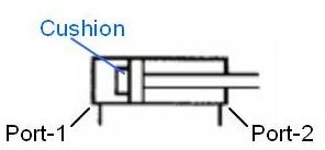
The symbol shown here is a double acting cylinder because it has two ports. Single acting cylinders have only one port. Hydraulic cylinders without cushions are also available.
5. Hydraulic Pump
Hydraulic pump is the heart of any hydraulic system. A pump develops pressure and thus fluid flows in the system. Pumps are represented as:
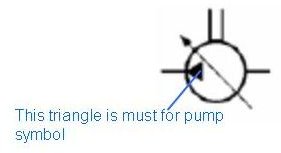
The angled line with arrow indicates that this is a variable displacement pump. A variable displacement pump can change the output flow volume without changing the pump’s RPM.
Conclusion
Huge lists of hydraulic symbols are available as per the ISO hydraulic symbol glossary. By understanding the five basic hydraulic symbols discussed here you will be able to understand many of the other symbols which fall under one of the five categories.
See Also
-
Design of Air to Air Heat Exchanger : As the name indicate an air to air heat exchanger exchange heat between air. This article will explore the function and design of air to air heat exchanger.
-
How a Compact Flat Plate Heat Exchanger Works : Plate heat exchanger or PHE is quite common in almost all industry. How a compact plate heat exchanger works? How a PHE is constructed? The article will explain all this.


