Moving huge weights used to be a big challenge for workers, which led to the invention of lifting machines. These well calculated, efficient mechanisms well allowed us to forge ahead into today’s modern industrial world. Let’s learn about a few of these intelligent mechanical tools.
Machines for lifting weights were basically invented for making the difficult tasks of maneuvering heavy objects easier for humans. The invention of wheels and pulleys were perhaps one of the major inventions which further helped to develop new innovative machines for lifting much heavier objects.
The ongoing research process always had one common goal with the development of these machines, to make them better and more efficient, technically to increase the respective mechanical advantages as far as possible. In simple words, a machine ideally should be able to operate heavier loads in response to smaller effort applied for the purpose.
In this article we will be discussing the following types of machines:
- Simple Wheel and Axle
- Differential Wheel and Axle
- Weston’s Differential Pulley Block
- Worm and Worm Wheel
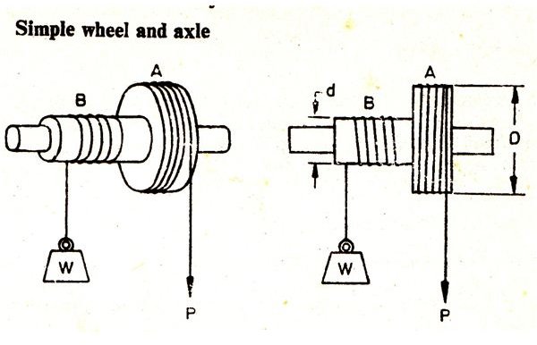
Simple Wheel and Axle
The figure shows a simple wheel and axle mechanism, having a wheel A and an axle B integrated together into one unit. Both the wheel and the axle are wound with strings, the end of the string over the axle carries a load while the free end of the string over the wheel is used for applying effort in order to raise the load attached with the axle string.
Since the directions of the string windings around A and B are in opposite directions, pulling of the wheel string downward lifts the weight upwards.
Let’s find the expressions for calculating the velocity ratio and the mechanical advantage of this machine.
Let D = Diameter of the wheel,
D = Diameter of the axle,
W = Weight attached with the axle string,
P = Effort applied for lifting the weight.
The wheel and the axle being attached together means that one revolution of the wheel would also produce one revolution of the axle.
The displacement produced through one revolution of the wheel due to the applied effort = πD,
Displacement of the load due to the above effort in one revolution = πd,
Since Velocity Ratio VR = Displacement of Effort / Displacement of Weight = πD / πd = D/d.
And Mechanical Advantage MA = Weight Lifted / Effort Applied = W / P (Standard Equation),
Therefore, the efficiency is given as ɳ = MA / VR
Differential Wheel and Axle
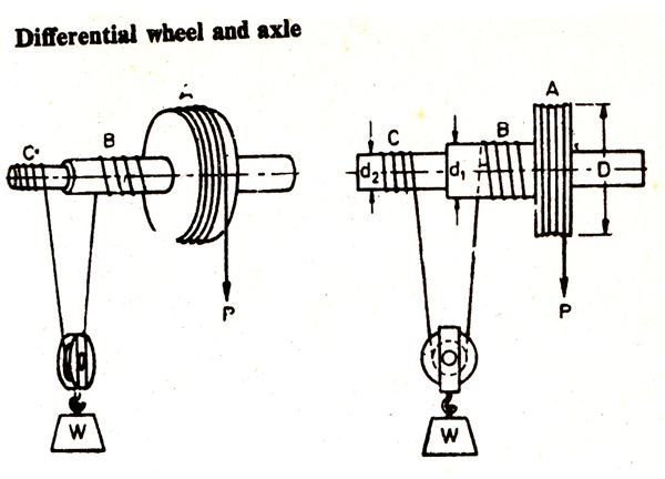
The figure shows a standard differential wheel and axle mechanism where the load axle consists of two parts B and C of different diameters. The effort string is wound about the wheel A. Another string is wound round the axles B and C such that the string passes through a pulley hung in between these axles. The pulley carries the weight which is to be lifted. The string is wound in opposite direction over B and C making sure C’s direction of winding matches with the wheel A’s string direction such that unwinding of the string over A also unwinds the string over C, but winds the string over B.
Let’s derive ways to calculate VR, MA and ɳ of the above machine.
Let D = Diameter of the Wheel A,
d1 = Diameter of the axle B,
d2 = Diameter of the axle C,
W = Weight being lifted,
P = The applied effort for lifting the weight.
One revolution produces a displacement of the effort = πD,
Therefore the length of string getting wound over the axle B and C through one revolution will be = πd1 and πd2 respectively.
However since the directions of the winding are different, the net length of the string wound across axles B and C will be = πd1 – πd2.
Therefore, displacement of the weight consequently will be = ½(πd1 – πd2)
And VR = πD/½(πd1 – πd2) = 2D/d1 – d2,
Also MA = W/P and ɳ = MA/VR
Weston’s Differential Pulley Block
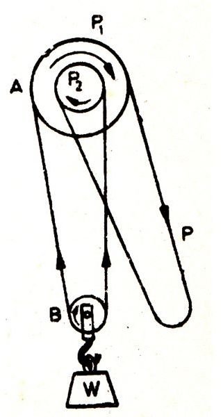
The figure shows an interesting machine where two sections A and B are wound through an endless chain mechanism. The upper block A consists of two pulleys P1 and P2, the latter being a little smaller in diameter. Because they form parts of a single wheel, move through the same direction when rotated. Another block B hanging downward supports the weight to be lifted. A circular chain without an end is wound across the two blocks through a smart inter-winding, first passing over P1, then the pulley B and finally through P2, the remaining endless portion of the chain hangs down and may be acted upon for lifting the weight. The pulley grooves are provided with projections which keep the chain locked and inhibits it from slipping over the pulleys while operating.
Let’s find the method of calculating the machine’s relevant parameters as discussed for the previous systems:
Let D = Diameter of P1,
D = Diameter of P2’
W = Weight required to be lifted,
P = Effort applied for displacing the weight.
Due to the applied effort P, the length of the chain crossing across the upper pullet block A = πD, which also equals the distance covered by the weight upwards.
Since the smaller pulley also turns proportionately, the chain displaced by it = πd.
The opposite displacements of the chain length is = πD – πd
The above shortening of the chain length is equally divided between the two halves of the pulley which supports the load.
Therefore the distance through which the load shifts = π/2(D – d),
Also the distance covered by the applied effort = πD
Gives VR = πD/π/2(D –d) = 2D/D – d
MA and ɳ is same as discussed previously.
Worm and worm Wheel
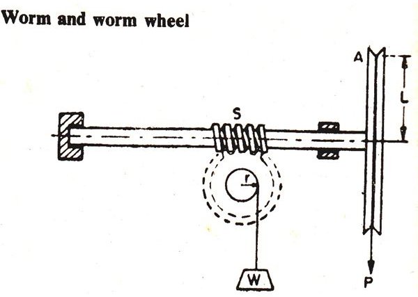
Referring to the figure, the mechanism consists of a spindle carrying a square threaded portion S at its center known as worm, which is geared to a wheel called worm wheel. The worm incorporates a secured drum and string mechanism for operating on the weight. A large wheel is fixed at the end of the worm spindle which carries a rope through its groove for taking the effort.
Let, L = Radius of the wheel,
r = Radius of the load drum,
W = Weight of the load,
P = Effort applied,
T = Worm wheel’s teeth number.
Considering the worm wheel to be single-threaded, for a single revolution of the wheel A, the central threaded section drives the worm wheel across a single tooth.
Therefore for every single revolution of the wheel, the distance covered by the effort = 2πL
The load drum moves across = 1/T revolution,
Therefore the distance covered by the weight = 2πr/T,
Therefore the Velocity Ratio = Distance covered by the effort/Distance covered by the load
= 2πL/2πr/T = LT/r
MA and efficiency formulas are same as discussed for the previous machines.
All images, Courtesy - Book - Applied Mechanics and Strength of Materials, By R.S. Khurmi,
References
Book - Applied Mechanics and Strength of Materials, By R.S. Khurmi,
Simple Machine, Wheel and Axle - rocketsciencetutors.com
Differential Pulley - en.wikipedia.org


