The centrifugal pump and positive displacement pump are the two primary categories of pumps. Centrifugal pumps are the most widely used, but there are a greater variety of positive displacement pumps, including gear pumps, peristaltic pumps, reciprocating pumps, screw pumps, and lobe pumps.
Types of Pumps
A pump is essentially a mechanical device that is used to move a fluid, normally uphill, or from a tank or reservoir. Pumps function by increasing the pressure of the fluid, so the pressure of the fluid exiting the pump is enough to push it uphill, into a tank, or wherever it is supposed to go. The main two classifications of pumps are the centrifugal pump and positive displacement pump. A centrifugal pump uses a rotating impeller to draw a vacuum at the inlet side of the pump and to send the fluid out at an increased pressure at the pump outlet. There are several different types of positive displacement pumps, including piston pumps, gear pumps, and peristaltic pumps. All of the positive displacement pumps physically draw fluid into the pump at the inlet and force it out of the pump outlet.
Centrifugal Pumps
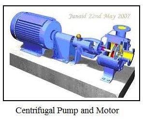
Centrifugal pumps are in very widespread use. The diagram at the left shows a centrifugal pump set up with a motor to drive it. The pump is partially cut away to show a bit about how it works. The diagram at the right shows a cutaway
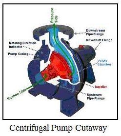
centrifugal pump diagram with the parts labeled. The pump impeller rotates within the pump housing (sometimes called the volute), thus causing a reduced pressure at the inlet (suction) side of the pump. The rotary motion of the impeller drives the fluid to the outside of the pump volute, increasing its pressure, and sending it out of the pump discharge, as shown in the diagram.
Both of these diagrams show a radial flow centrifugal pump, which has the flow pattern just described above. This is the most common centrifugal pump flow pattern. Another alternative is the axial flow centrifugal pump, which has an impeller shaped somewhat like a propeller, that draws fluid in along the pump axis and sends it out along the axis at the other side of the pump.
Image Credits: Centrifugal Pump and Motor - Wikimedia Commons ; Centrifugal Pump Cutaway - Wikimedia Commons
Positive Displacement Pumps
A positive displacement pump forces a predetermined fluid quantity from the pump inlet to the pump discharge for each pump cycle. These pumps produce a pulsating flow, with periods of fluid delivery separated by periods with no fluid delivery. This effect is less pronounced with some types of positive displacement pumps. Unlike centrifugal pumps, these pumps supply the same fluid flow at a specific speed, irrespective of the discharge pressure. A positive displacement pump should not be run with the discharge valve closed. A centrifugal pump that is pumping against a closed valve will just build up to some maximum pressure for that pump, but a positive displacement pump will continue to discharge fluid into the fixed volume ahead of the closed valve until the line busts or the pump is damaged. Therefore, a discharge relief valve, or safety valve, is essential. An external discharge relief valve is normally installed, with a line returning to the reservoir. Positive-displacement pumps are sometimes grouped into three categories: rotary pumps, reciprocating pumps, and diaphragm pumps. Each is discussed briefly in the next several sections
Rotary Positive Displacement Pumps
Rotary positive displacement pumps draw fluid into some type of chamber, which is then moved around by the rotary action of the pump from the inlet to the outlet of the pump, where the fluid is discharged. The clearances between the moving parts are typically close, so the pump speed must be kept relatively slow. If these pumps operate at excessive speeds, erosion will be caused by the fluids, like polishing of stones by ocean waves. Excessive clearances are created due to such erosion that permits slip of liquids, decreasing the pump efficiency. Several types of rotary positive displacement pumps are described next.
Gear Pumps
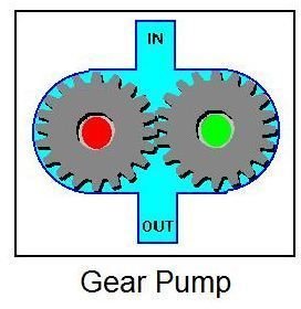
Gear pumps consist of gears that are arranged with the teeth meshed, as shown in the diagram at the left. The gears rotate in opposite directions, so that they pull fluid into the spaces between the gear teeth and the pump casing. The fluid is finally released through the pump discharge due to the movement of the teeth. A fairly constant fluid flow is maintained by smaller teeth, while bigger teeth will produce a more pulsating fluid flow pattern.
Image Credit: RPI Chem Engr Dept
Lobe Pumps
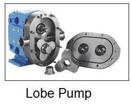
The principle of the lobe pump is very similar to that of the gear pump, except that a smaller number of larger “lobes” mesh together as shown in the diagram of a disassembled lobe pump at the right. In this case the fluid is moved through the pump in spaces between the lobes and the pump casing.
Image Credit: MSU Engineering
Screw Pumps
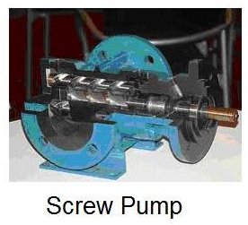
Screw pumps are fitted with two screws that have opposite threads, one turning clockwise while the other turns counterclockwise. The screws are fixed on parallel shafts that have meshed gears. The shafts are rotated due to the gear movements. The fluid is drawn from the pump due to the screws turning. The clearance between the moving components and the pump casing is necessarily quite small.
Image Credit: Wikimedia Commons
Peristaltic Pump
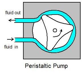
Peristaltic pumps, also sometimes called tubing pumps, don’t quite fit the general description of rotary positive displacement pumps given above, but this is still the closest classification for them. For this type of pump, a rotor with lobes squeezes tubing against the inside of a cylinder as it rotates and thus draws fluid through the tube. The principle is illustrated in the diagram at the right.
Image Credit: H. Bengtson
Reciprocating Positive Displacement Pumps
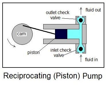
Reciprocating positive displacement pumps, also called piston pumps, are used for many vacuum pumps. The pump consists of a cylinder and piston with two one-way valves, one at the inlet and one at the outlet of the pump. On the suction stroke of the piston, the discharge one-way valve is drawn shut and the inlet one-way valve opens due to the suction in the cylinder, thus drawing fluid into the cylinder. As the piston reverses direction and begins the discharge stroke, the inlet valve is pushed shut and the outlet valve is pushed open, so that fluid is pushed out of the discharge port of the pump. This is shown in the schematic diagram at the left.
Image Credit: H. Bengtson
Diaphragm Positive Displacement Pumps
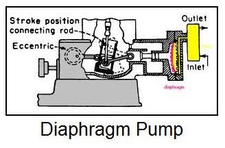
A diaphragm pump is shown in the diagram at the right. Fluid is drawn in when the diaphragm is pulled back and the fluid is forced out when the diapragm is pushed forward. One-way inlet and outlet valves are needed as shown in the piston pump diagram above. The reciprocating motion of the diaphragm may be caused by a camshaft and piston, as shown in the diagram, or it may be caused by compressed air, or by a pulsating fluid pressure from some other source. A useful feature of the diaphragm pump is that the fluid being pumped is completely isolated from the drive mechanism. There will be no leakage past seals, etc., as is possible in many other types of pumps.
References
1. _B_engtson, H, Centrifugal and Positive Displacement Pump Basics , an online, continuing education course for Professional Engineers.
2. Bengtson, H., Improving Performance of Pumping Systems , an online, continuing education course for Professional Engineers.
3. Evans, J., A Brief Introduction to Centrifugal Pumps , Pacific Liquid & Air Systems


