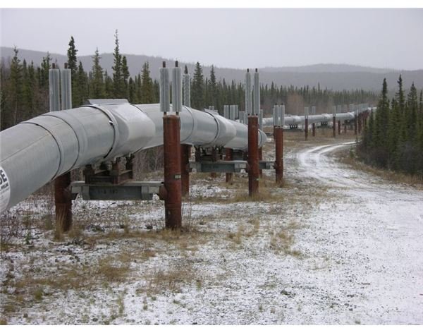
The Alaska Pipeline runs from Prudhoe Bay to Valdez; a distance of 800 miles, and has been transporting local crude oil since 1977, using up to ten pumps. About half of the insulated, large diameter pipeline is supported above ground by specially designed supports, with the remainder being buried.
Crude oil becomes very viscous at low temperatures; therefore methods have been developed to power the Alaska pipeline, keeping the oil at 180F, hot enough to pump, since 1977.
Alaska’s first oil was discovered at Swanson River Field in 1957, followed by the Cook Inlet fields in 1962, but it was in 1968 that America’s largest oilfield was discovered at Prudhoe Bay. This eventually led to the construction of the Alaska Pipeline which began transporting the crude oil from Prudhoe Bay to Valdez in 1977.
The pipeline is 800 miles long and fabricated from heavy wall cold weather steel pipe of 48” diameter in lengths of 40 and 60’, imported from Japan.
There were 11 pumping stations containing 4 pumps per station. However, they are not all on-line at the same time; for example for a throughput of 200 million barrels/day, 7 pump stations are used, the other ones being on standby or out for maintenance.
Elevated and Buried Sections of the Alaska Pipeline
Soil samples were taken from locations along the proposed route of the pipeline. Following are examples of the pipeline design to cope with these soil conditions.
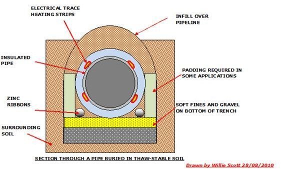
1. Thaw-Stable Soil
This soil condition allows the pipeline to buried in the conventional manner, consisting of digging an 8’ wide trench to a depth of 8-16’, and infilling with layers of non-sharp fines, gravel and fine loam, buffer board packers being used as required.
The pipes are laid on top of this with sacrificial zinc anode ribbons laid alongside them. As well as being an anticorrosive measure, these zinc ribbons also act as telluric current conductors, returning any electric current picked up back to earth.
2. Thaw- Unstable Soil
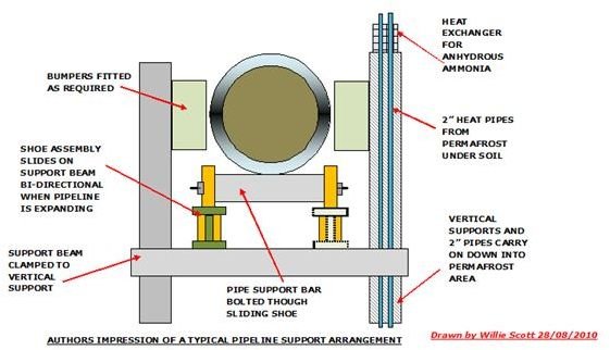
If this permafrost is disturbed by heat subsidence will occur, so the insulated pipeline is installed well above the soil, on specially developed supports.
In hot permafrost areas where the heat may also cause subsidence and affect the pipe supports an additional method is employed to keep the permafrost from melting.
This consists of inserting two pipes into the permafrost containing a solution of anhydrous ammonia that vaporizes in the permafrost. The vapor rises up the pipes before condensing in a heat exchanger integral with the vertical support leg, maintaining the ground temperature below the air temperature.
3. Special Soil Conditions
i. In permafrost soils where for various reasons the pipeline was required to be buried, the pipes were insulated to a thickness of 4” and buried in the normal manner.
ii. Some locations required the pipeline to be buried in a refrigerated trench; here the pipes are insulated and buried as above. Brine refrigeration is circulated around the trench through 6” pipes to maintain the condition.
Installation of the Alaska Pipeline
Pipe Specification
- Lengths
The pipeline was fabricated from special cold-weather steel pipe, in 40 and 60’ lengths.
- Grades
1. API Grade X60:0.462 wall thickness.
2. API Grade X65: 0.562 wall thickness.
3. API Grade X70: 0.562 wall thickness.
- Insulation
- Above Ground: 3.75”
- Refrigerated below ground:3.2”
- Under gravel or road: 2-4”
Therm-O-Trol: Polyurethane foam produced by GEC is used on the pipeline.
- Trace Heating to Maintain 180°F
Skin trace heating strips are fixed to the outside of the pipe before insulation is applied.
- Thermal Expansion
As the pipeline expands and contracts; this is counteracted by laying the pipes in a zigzag pattern, the supports having sliding shoes to accommodate this movement.
- Intelligent Pigs
These are inserted to inspect the inside bore of the pipeline for corrosion, stress, or deformity. They are pushed along the pipeline by the pressure of the oil, transmitting their data back to the control room.
- Cleaning Pigs
These pigs are inserted periodically to clean the sludge and wax from the inside of the pipeline.
Powering the Alaska Pipeline - Pumps and Stations
As well as housing the pumps, the pump stations also have power generation units, delivering between 1MW and 4MW of power to the system.
The original design was for 12 pump stations, but only 11 stations were eventually built, with each station having four pumps.
At start-up 8 stations were being used and this increased to 11 stations as production rose and throughput was able to be increased. However over the years this has decreased to 4 stations, (with one station on standby) each station having a pumping capacity ranging from 20,000 to 60,000 gallons/min at a pressure of just over 1,100 lbs/square inch.
Gas turbines of up to 17000 hp drive a mix of full head and half head pumps, depending on the pipelines topography.
- Full head pumps – twin impellers in series; delivers twice pressure at half flow rate.
- Half head pumps – twin impellers in parallel; twice the flow rate at half the pressure
As of 2010, pump stations 1, 3, 4, and 9 are delivering 650,000 barrels of crude oil per day along the pipeline to Valdez.
Images Gallery - Sketches of Alaska Pipeline showing Underground and Elevated Locations
References
- millerwelds - pipe specs and welding techniques.
- Reference Web: alaskastock - general information on Alaska.
- ameref - types of pumps.
- alyeskapipe - pipeline information.
- alyeskapipe - engineering of pipeline.
- solocomhouse - engineering information.
- ep2000 - trace heating of pipeline.
- adn - current pumping stations and capacities.
- Photo of Alaska Pipeline by Ryan McFarland from Petersburg, AK (DSCN4804) [CC-BY-2.0 (http://creativecommons.org/licenses/by/2.0 )], via Wikimedia Commons
- alyeskapipe - intelligent pigs.


