This Pro Engineer Mechanica tutorial will discuss about buckling analysis of a steel plate. You will come to know what is buckling FEA and how to perform it for a steel plate using the Pro Mechanica module of ProE.
The buckling type of FEA can be performed using the Pro Engineer Mechanica or Pro Mechanica module of the ProE. By using Pro Mechanica tool you can perform only linear types of buckling analysis. We will see the example of buckling analysis of a steel plate.
What is the Use of Performing a Buckling Analysis?
In simple term, by performing buckling analysis using Pro Mechanica you will come to know about the buckling factor value for the structure. And, by multiplying the buckling factor value to the present load value you will get the critical buckling load for the structure. Critical buckling load is the minimum loads require initiating buckling.
How to Perform Buckling FEA using Pro Mechanica
For performing a buckling analysis you have to perform a static analysis first then using the result of the static analysis , buckling analysis is performed.
Performing Static Analysis:
- Build the ProE geometry of the structure using standard ProE module.
- Bring the geometry to the Pro Mechanica module, for that go to Application>Mechanica.
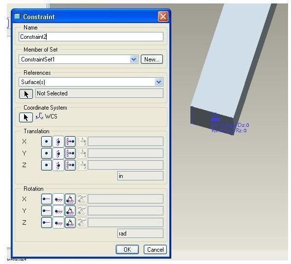
- Apply the constraints, for that go to Insert> Displacement Constraints; the constraint dialog box will appear. You have to select the surface, where you will apply constraints.
- In our example, we will analyze a steel plate and will apply constraints at the bottom surface of the column like below:
The blue triangles of the picture indicating the constraints.
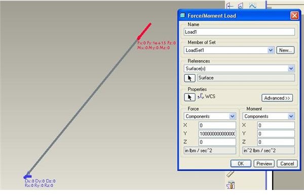
- Next, you have to apply loads by going to Insert> Force/moment loads, in the above example we will apply loads on the top surface of the plate. See below:
- Apply the material property to the column by Properties>Materials.
- Mesh the column by going to AutoGEM>Create.
- Now, open the Analysis and Design Studies dialog box by going to Analysis>Mechanica Analysis/Studies. Further go to File> New Static of the Analysis and design studies dialog box. “Start Run” by clicking the Green flag of the dialog box, then click the Display Study Status icon, it will show when the run is complete.
- Save the static analysis by save button of the ProE window.
Performing Actual Buckling Analysis of the Plate:
- After performing the static analysis, again go to the file tab of the Analysis and Design Studies dialog box click the New buckling option. The buckling analysis definition dialog box will appear as below:
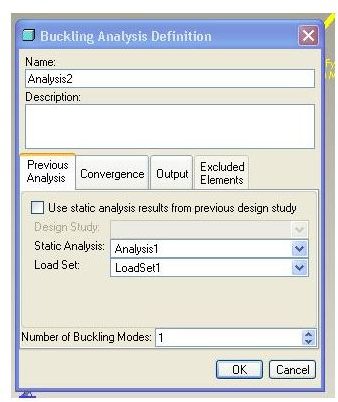
Increase the number of buckling modes to 5 and click OK. The dialog box will disappear.
- Now click the Start Run (green flag) icon of the Analysis and Design Studies dialog box.
- Next, hit the Display Study Status icon and finish the run.
- Now, click the last icon of the Analysis and Design Studies dialog box, that is Review Results icon and you will see the Result window definition dialog box appears like below:
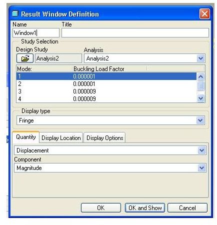
- Now you can see any of the five mode shapes by clicking the respective mode number and then clicking the Ok and Show button. You can also see the buckling load factor displayed next to each mode number. For the same load if you decrease the length of the steel plate, you will see the buckling load factor will increase accordingly, Means, you have to apply comparatively more load to buckle a shorter plate.
Conclusion
Using Pro Engineer Mechanica module of ProE a mechanical design engineer can quickly perform the buckling analysis of a steel plate or any structure. Though, the Pro Mechanica approach is bit more conservative but still very handy for the design engineer.


