Pro Engineer is developed in such a way that the feature operations in ProE are actually similar to real life manufacturing operations. Form feature in Pro Engineer is identical to the real life sheet metal forming operations (where components are produced by sheet metal punch and die press tools).
Some basics about sheet metal forming operations
You may have noticed the small louvers over your PC’s CPU cover or the stainless steel dishes in your kitchen. Both are examples of sheet metal formed components. In this process, flat sheet metal is placed between a die and punch, and the shape is quite literally hammered into the metal. The output of the forming process is usually very high and so has a very low production cost per unit.
How sheet metal forming components are designed in ProE
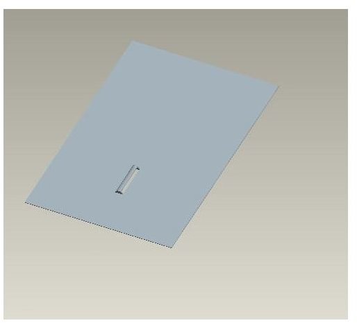
A very user-friendly command called create form is used for designing formed components in Pro Engineer. The point to be noted here is that you can use either a sheet metal punch or a die, but not both, to create a sheet metal forming feature in Pro Engineer. Suppose you need to create a louver in the sheet metal component as in the snapshots below (click on them to enlarge):
The louver can be designed by using the punch as well as the die option. In both cases, you need to model a part which can be used as a die or punch.
By using the die option:
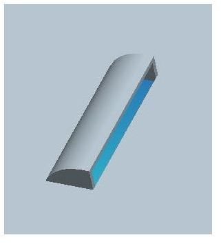
- The die part (say, d.prt) should look like below:
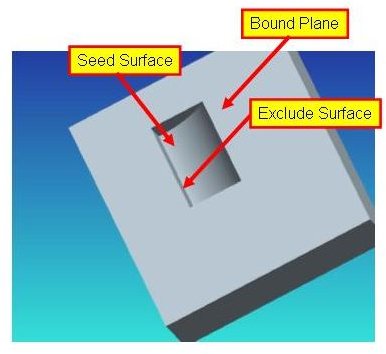
Select the die part (d.prt). Assemble the d.prt with respect to the sheet metal part using assembly constraints. Make sure it is fully constrained. Select the Bound Plane and Exclude Surface as shown. Select the vertical face as Exclude surface, so that opening of the louver is created.
- In the sheet metal mode of ProE go to insert → shape → form → die → done
By using the punch option:
- The punch part(say p.prt) should look like:
- Go to insert → shape → form → die → done.
- Select the p.prt.
- Assemble it suitably with respect to sheet metal part in order to make it fully constrained.
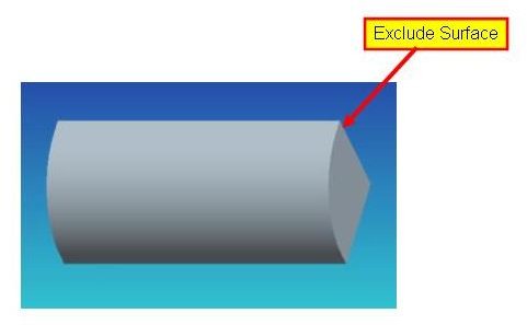
- Select the vertical face as exclude surface in order to create the opening of the louver.
Difference between Die and Punch in ProE
- Ideally, the die should be modeled as female part and the punch as male.
- The whole die part is not used to create the form feature in ProE. From Bound Surface to Seed Surface portion of the die part is only used. However the whole part is used for sheet metal forming operation in case of a punch.
Conclusion
The sheet metal forming operation in ProE is quite similar to the real world forming process. The only difference is in case of ProE is that either a sheet metal punch or a die be used at a time for creation of sheet metal forming components.


