When you are creating sketches in SW2008, you should not only take full advantage of sketch dimensioning, relations etc. – but also may use more advanced features. One of such features in SolidWorks is “offset” – using the previously created contour/line to define your sketch.
Introduction
Many features have been designed by SW programmers to help you in creating sketches. Even more attention have been given to editing sketches – providing some very useful options – including the “offset” feature that will be overviewed in this article.
Introduction
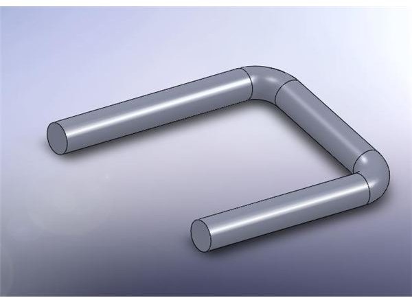
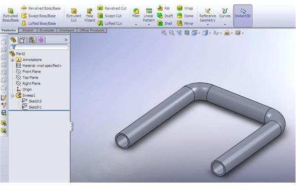
Suppose that you have the part that looks like a the one above. Suddenly, you are required to make a “hole” in it – converting the rod into a tube. Of course, there is an option to edit the sweep feature so it will become ”thin-walled” sweep. There is also an option of creating extruded cut. But we want to examine another way to do it – using the already created sweep feature and altering it’s “profile” sketch.
Rod and Tube
Introduction
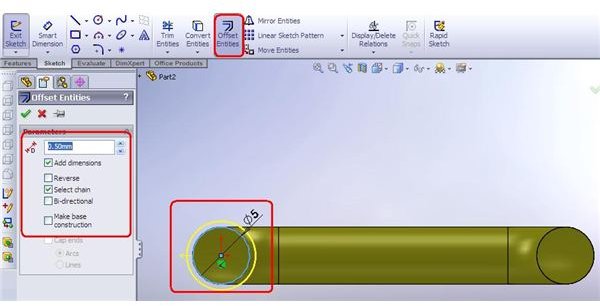
Let’s click on the profile sketch and show it. Then click on “edit” and set the view to “normal to” current sketch. Now, we could just draw another circle and set it’s dimensions. However, we would like that our circles would be interrelated.
Thus, we will use the “offset” – feature – defining the difference between the 2 circles inside the sketch.
To do that, pick the constructed circle. Now go to sketch menu and click on offset. (by, the way, those 2 steps can be done vice-versa as well).
Note, that you have the preview of you “new circle” in yellow. Set the offset distance. Once you click either inside or outside the circle – a new contour will be created, which will be relative to the initial circle. Exit the sketch – and see the sweep feature updatedto produce the required “tube”.
Introduction
Offset Options
There are also other offset options:
- “Reverse offset” – allows you, instead of clicking inside/outside the initial contour to choose the direction of the offset
- “Bi-directional offset” will provide 2 offset contours – one inside and one outside the initial.
- “Select chain” – very useful for complex contours – allows you to select the completed contour with picking only one line of it.
- “Make base construction” – makes the initial contour a “for construction” one – setting it as a reference. Very useful when used together with “Bi-directional offset” – producing 2 new contours and setting the initial profile (circle) as a mid-line.


