Creating sketch relations in SolidWorks is a useful must-learn option. This article continues the overview of understanding the process of setting the interaction between sketch entities in order to completely define your sketch. It deals with circles and mid-plane extrusion.
Introduction
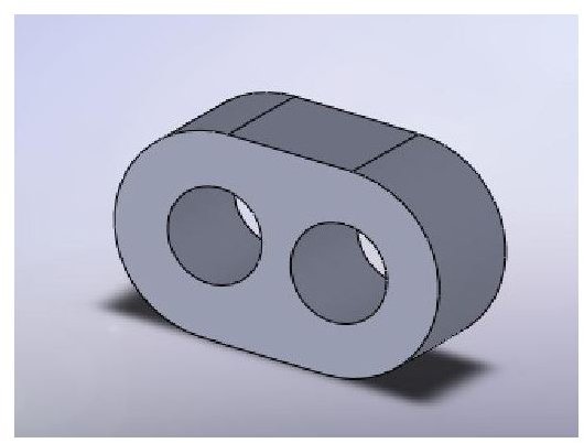
In previous article, we have started our way to the construction of this part (pictured below) and also completed a sketch that has 2 horizontal lines and 2 tangent arcs – the pairs being of equal radius/length.
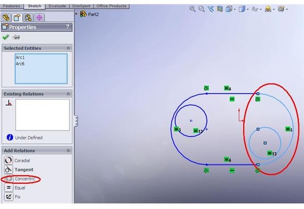
Concentric relation
Now, we would like to define the 2 holes, which are concentric with the arcs. To do that – just draw 2 circles and set their relation to “Equal”. This will save you time later in dimensioning process. Now, pick one circle and one arc and click the “Concentric” relation. Repeat the task for the second circle and arc.
Construction Line
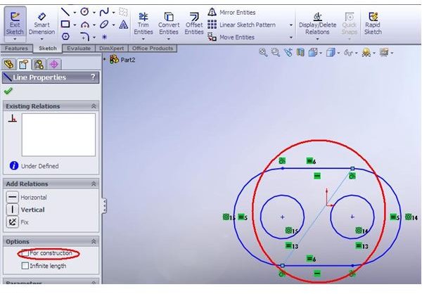
The sketch is almost ready – but we now want to center it about the origin point. To do that we will construct a “supporting line” - a line which connects 2 opposite points (upper-right with lower-left or vice-versa). After you have created a line – click on it. In the left portion of the screen – mark the “for construction” option – the line will become dashed. (You could also define the line as “center line – which is a construction line – when selecting line from the sketch menu).
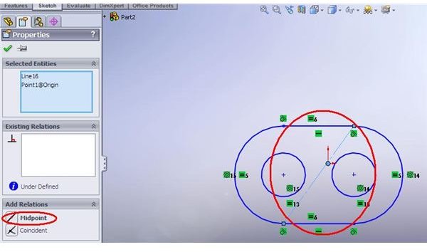
Mid-point Relation
Next, pick both the line and the origin point (hold CTRL to select multiple entities). This is the line-to-point relation. Pick “Mid-line” option – and your sketch will be now positioned with origin point in its center. Now define the necessary dimensions – and the sketch is ready! Notice that the sketch is now black – which means it is “fully defined” – not only completely dimensioned but also positioned relative to the sketch plane.
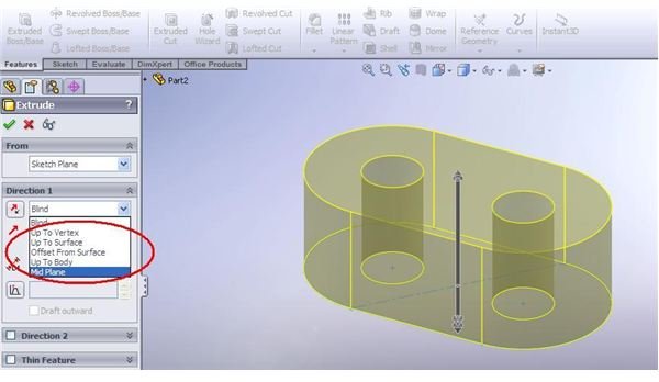
Mid-Plane Extrude
In the last step – we will make the symmetric extrusion of the sketch – in order to stay centered around the origin. Select your sketch and click “Extruded Boss/Base”. In the direction select the “Mid-plane” option. Last, define the length of your protrusion – and that’s it! Your part is created, positioned perfectly in the middle of the “universe” – which will surely be helpful when bringing it to the assembly and defining assembly mates.
More to come
Generally, that completes the overview of sketch relations. However, to make thing more “sorted”, we will present you a summary of all the relation options in the next article.


