There are several types of waste incineration plants. The most common type is municipal solid waste (MSW) with the heat providing energy from waste. This is becoming more necessary in many countries throughout the world as we all run out of land-fill sites for our household rubbish.
Incineration of waste is not a new process, but the rules and regulations regarding emission of the resultant pollutants to the atmosphere have been tightened and upgraded. This is due to the fumes produced containing dioxin particulates and heavy metals, both of which are dangers to public health.
The following sections examine the incineration of municipal solid waste incorporating a waste heat boiler to recover some of the energy from waste (EfW). The first section gives a brief overview of waste management techniques and strategies.
Waste Management – an Overview
Waste management plays an important role in the disposal of our waste in an environmentally efficient, safe manner.
There are a number of basic means of disposing of our waste.
- Recycling
Here materials such as paper, glass, plastic, aluminum, and tin cans are sorted by the householder and collected from the curbside outside their property. Vegetation, grass and hedge clippings are collected for composting; the remaining waste is sent to a landfill or an incineration plant.
- Incineration (after sorting)
Here the recyclable materials are removed before incineration as per the above method.
- Incineration (non-sorted)
In this method all the municipal waste is incinerated without segregation of recyclable materials, with the ferrous metals being extracted from furnace bottom ash by magnets.
- Landfill
Land-fill usage is either banned or being phased out in major countries of the Western World. DOE and EU legislation has made this method of disposal very expensive through the introduction of a levy per ton for disposal. At the same time, old disused landfill sites produce a gas that can be processed to run gas turbine/engines driving electric generators providing power to the local grid.
- Gasification
The MSW is fed into large steel digesters that are free from oxygen and light and heat are applied. The organic waste breaks down through time producing a gas that can be used to run a gas turbine/engine driving an electric generator.
- Incineration - Energy from Waste (EfW)
All new plants are required by law to incorporate some form of EfW system through using the heat produced to run a waste heat boiler or a district/community heating system.
The next section examines one such method for the incineration of municipal solid waste using a waste heat boiler as a means of recovering energy from its combustion.
Characteristics of Waste Incineration Plants
Municipal solid waste incineration is basically a waste treatment process that involves the combustion of waste as an alternative method to using the scarce number of remaining landfill sites.
Some facilities practice recycling techniques where the recyclable materials are sorted (mostly still by hand) from the incoming waste before being segregated, bagged, and transported to one of the various recycling plants. The remaining waste is tipped into a storage pit from where it is loaded into a hopper on the side of the furnace by an overhead gantry crane.
The furnace consists of a rectangular steel box lined with fire-brick on the inside and insulated on the outer shell. Oil/gas burners/registers of normal boiler furnace design are fitted, and these project the flames towards the floor of the furnace. Running along the floor of the furnace is a steel-link fire grate that is mechanically driven, picking up the waste at one end from under the loading hopper and, through providing a combustion bed, burning the waste as it moves along the floor. At the end of the grate, the waste that has by now turned to ash falls off the grate into a quench tank. From here it passes under a magnet to remove any ferrous metals before passing into a storage hopper.
This residue is known as bottom ash. Along with fly-ash, it contains a large portion of the heavy metals such as lead and cadmium. The ash is sent to a landfill or, better, used as aggregate in the road construction industry.
Combustion air is provided from a forced draft fan that supplies the air to the grate, helping to break-up and mix the waste. This along with the air supplied to the furnace burners ensures complete combustion of the waste, albeit in excess air. Complete combustion takes place at around a temperature of 550°C. Along with this, recent EU directives call for temperature of 850°C to be maintained for 2 seconds per new load, eliminating any bacteria/viruses contained in the new charge of waste.
Water-tubes that form part of a normal waste heat boiler system are fitted inside the furnace in the path of the hot combustion fumes. A superheater is also positioned in this pathway, before the combustion fumes exit from the roof of the furnace.
The fumes are now subjected to fume treatment that consists of components in the following order:
- Gas Cooler - The gases are still at a high temperature; exiting the furnace after the waste heat boiler at around 200°C. So, before passing to the treatment plant proper they are cooled using a normal water tube cooler.
- Particulate Filtration - These minute particulates being assigned a PM10 category are particularly dangerous to us humans as they clog up the respiratory and vascular systems, especially that of the elderly and babies.
There are several methods of removing/reducing them from the gas-flow.
- Bag-house Filters
These fabric-mix filter bags are installed in the bag-house, being open at one end to allow the fumes to enter. As the fumes pass through the bags, the particles and fine dust are trapped; falling down into a storage hopper in the base of the housing. These are very efficient filters capable of removing up to 95% of PM10’s and fine dust from the fumes.
Many years ago I was an engineer in a copper smelter in Northern Rhodesia, being responsible for the maintenance of the waste-heat boilers that ran off the copper smelting furnace. The fume treatment had not worked for a long time due to lack of spares and the indifference of the workforce to the fumes that were emitted from high brick chimneys. Sulfur was extracted from the fumes through processing in an acid plant, but the particulates and other heavy metals went straight up the chimney-dropping from the resultant plume to land on the local townships and shanty towns. I did manage to get some sort of particulate and fine dust extraction working along the lines of a bag-house filter unit, but that’s another story.
Today’s filter bags are very robust, being manufactured from durable fine woven fabric materials that can promote a large reduction in particulate and dust emissions.
The bag-house also has an automatic self-purging/cleaning operation using compressed air to ensure efficient operation.
- Electro Static Precipitator (ESP)
This component utilizes the properties of a negative and positive DC current to collect the particulates on steel plates. Once the plates are full, a hammer head strikes the plates releasing the particulates/dust to fall into a hopper at the base of the unit.
3. Scrubbers
A wet scrubber consists of a vertical steel tower with the fumes entering at the bottom and passing upwards. A solution of lime and water is sprayed into the path of the fumes removing the sulfur oxide and some of the dioxins (produced from combustion of plastics). These all fall to the bottom of the scrubber forming a slurry of calcium sulfate – (gypsum). This is the material used for producing wall boards, and it is sold off to the building industry.
4. Gas Drier / De-activated Carbon Unit
The fumes leave the wet scrubber and enter a drier to remove the moisture before passing through an activated carbon unit/dry scrubber that extracts more heavy metals from the fumes.
5. Fume Extraction Fan/Chimney
The fumes are drawn through the activated carbon unit by a centrifugal fume extraction fan that forces them into the chimney. (Some systems incorporate fine, high-pressure water sprays inside the chimney).
From here the fumes, still containing various pollutants, are propelled high into the atmosphere where they form a plume before dispersing and falling to the ground.
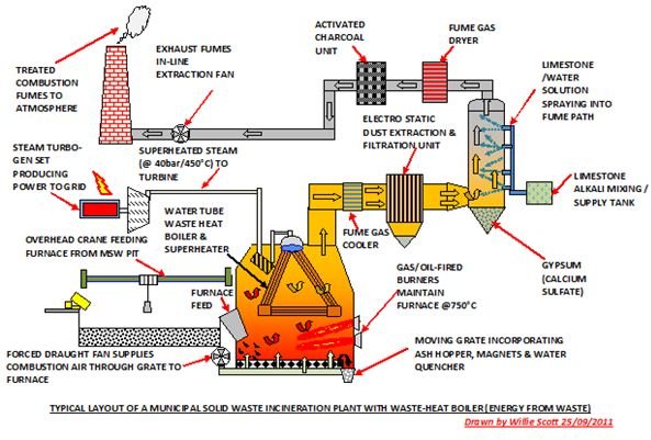
The layout of key components of a Municipal Solid Waste Incinerator is shown below. (Please click the image to enlarge.)
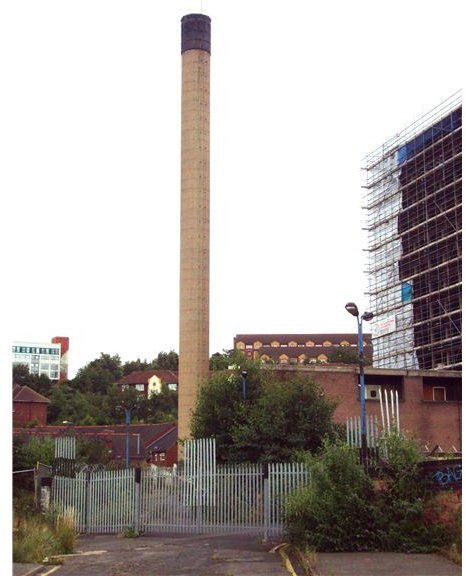
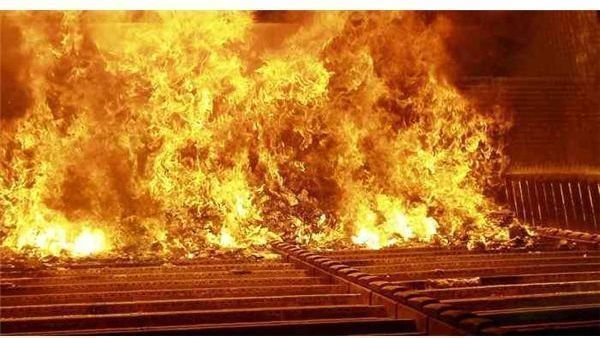
Below, a typical chimney and an example of a fire bed/moving grate in operation.
References
- Waste incineration: An Effective Waste Management Solution?
- nytimes: Burning Trash
- EPAgov: Regulation and Lays on Waste Disposal USA