LED Constant Current Maintenance - Current Stabilization in LED Circuits Expounded
Introduction
Light Emitting Diodes (LEDs) have become very common nowadays. It is mostly used as power indicator in electronic appliances. They are also widely used in decorative lighting and advertising displays. The interesting feature in LEDs is they emit quite a bit of light even at very low currents. But this also means that it can get permanently damaged at high a LED current. Moreover a higher LED current than the required quantity will result in unnecessary heating of the LED, lowering its efficiency and life in the long run. Thus it becomes imperative that some kind of LED current limiting facility is provided to have LED constant current flow for optimum results. This is very normally achieved using a series resistor.
How to Calculate the Value of Current Limiting Resistor?
It can be done simply through the below given formula:
R(x)=V(s)-( n.V(led) ) / I(led)
Here R(x)=value of the LED current limiting resistor,
V(s)= supply voltage,
n=no. of LEDs in series,
and I(led)=current through the LEDs.
Since V(led) is different for different colored LEDs, it will obviously depend on what color LED you are using.
Normally the minimum voltage required to light a red Led is 1.7V, for green it’s 2V and for yellow it is 2.5V. The LED current may be selected between 10ma-50ma, depending upon the required intensity.
The idea of a series current limiting resistor is a straight forward one but some energy is wasted in it in the form of heat. Moreover the current through it is not stabilized and the LED connected isn’t safe in case the voltage rises.
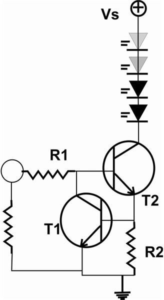
How to Stabilize LED Current
With the help of a couple of transistors and resistors the LED current can be checked. Here T1 forms a current source for the LED and R1 is used for biasing the base of T1.
Resistor R2 is dimensioned in such a way that a potential difference of at least 0.6V is formed across it, if the current starts rising beyond the tolerable limit. Due to this T2 starts conducting, bringing down the base current of T1 which in turn stops the excess flow of current through the LEDs, or in other words the value of R2 is selected such that at normal conditions the potential drop across R2 is just under 0.6 volts.
The value of R2 is calculated as under:
R2=0.6/I(led)
here I(led)= maximum tolerable LED current.
Calculating R1 is also very easy,
R1=( V(b)-0.6 ).Hfe / I(led),
here V(b)=source voltage to R1,
Hfe=forward current gain of T1 used.