How to Build a Home Made Frequency Meter - Includes Schematic and Parts List
Introduction
The frequency meters available in the market are generally too costly and sophisticated. For new electronic enthusiasts it is always difficult to lay their hands on these hi-end types of frequency meters. Also, since the measuring needs of these electronic novices are limited, a simple analogue frequency meter in most cases can easily fulfill their demands. The homemade frequency meter circuit described in this article is very simple in design and will provide an optimum frequency measuring range useful to most electronic hobbyists. Moreover it would be great fun to build a test instrument at home and use it for the testing purposes of the future construction projects.
What is Frequency?
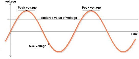
In electronics, a frequency generally is in the form of a voltage that changes or varies its polarity number of times per second. You may take the example of your domestic mains AC line where the frequency of the voltage changes from positive to negative 50 to 60 times a second, hence the name Alternating Current or AC.
The frequencies involved in electronic circuits are always low in magnitude and may not exceed the maximum operating voltage or the supply voltage of the circuit itself. These are used to fulfill many complicated functions in a circuit and are mostly generated using CMOS logic gates. It often becomes necessary to measure the rate of these frequencies and thus a frequency meter proves to be quite an indispensable tool for it.
The circuit of an analogue frequency meter presented here can be used to measure frequencies from as low as 25 Hz to a maximum of 500 KHz.
Circuit Description
To understand the circuit functioning of this homemade frequency meter, let’s go through the following explanation:
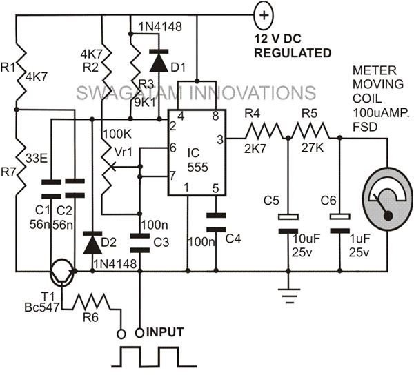
IC 555 forms the main part of the circuit and is wired as a monostable multivibrator.
Its frequency is determined by the external components R2, VR1 and C3. The setting of VR1 is important and may be used to adjust the measuring range of the frequency meter.
The frequency in question is applied to the base of transistor T1 via resistor R6. T1 conducts only during the positive peaks of the input oscillations.
During these conductions of T1, capacitor C2 is forced to discharge quickly through R7 and T1. Also, during the negative peaks of the input oscillations, T1 is cut OFF and now C2 charges via R1 but at a fairly slow rate.
Due to this, a sharp negative pulse appears at pin 2 of the IC through the capacitor C1. Resistor R3 makes it sure that the pulse is narrow and only just triggers the IC.
The IC immediately responds to the trigger generating a pulse of a constant period set by VR1 at its output pin 3.
This pulse is smoothed and integrated by R4, R5 and C5, C6 to produce an average value of the pulses. A moving coil type meter can be used to indicate this integrated value.
The magnitude of these pulses will linearly vary with the input frequency and thus can be directly measured over the meter.
Waveform Image Credit: https://www.bbc.co.uk/scotland/learning/bitesize/standard/physics/images/waveform2.gif