Steam turbines are one of the major drivers of power generators in today’s power plants. There are several types of turbines and a number of mechanical arrangements to obtain maximum efficiency and output. The auxiliaries however are very similar, performing equally important tasks in their systems.
Steam Turbine Auxiliaries
Introduction
In the previous article on power plant auxiliaries we looked at the important part played by the auxiliaries of a dual drum water tube boiler.
Following on from there, here we will examine the main auxiliaries of the associated steam turbine, using the same method of locating and describing the functions of the different components within the relevant systems.
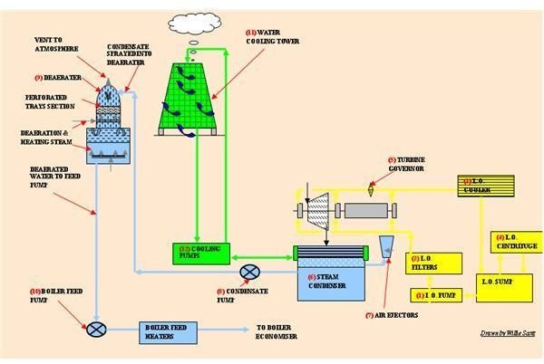
Please refer to the drawing to when reading the component descriptions which are numbered in sequence as in the descriptions.
Lube-oil System
1. Pumps
The lubricating oil system has three separate pumps which supply the bearings and hydraulic system with oil.
- Lube oil Jacking pump – this is used when the turbine is being rotated by the turning gear.
- Emergency Lube oil Pump – this cuts in if the turbine trips through loss of power.
- Lube oil Booster Pump – this pump is used at start-up and ensures an adequate flow at slow speeds. It cuts out when the turbine reaches operation speed
- Main lube oil pump – this pump draws the oil from a lube oil tank and supplies the turbine bearings and governor. This is normally a centrifugal pump driven by the turbine or generator shaft.
2. L.O. Filters
Some systems have duplex filters on the suction and discharge pipework of the pumps, but at a minimum a set on the discharge. These remove any debris picked up by the oil before the oil is fed to the bearings.
3. L.O. Coolers
The oil lubricates the bearings absorbing the heat from friction. This heat is dissipated by the coolers. These are usually tube coolers, water being the medium used to cool the oil.
4. L.O. Centrifuge
The centrifuge is usually positioned above the lube oil tank and runs continually whilst the turbine is operating, only coming off line for cleaning. It draws the lube oil from the lube oil tank removing any water and particles by centrifugal force before discharging the clean oil back to the tank.
5. Turbine Governor
As the loads on the generator vary requiring more or less steam to the turbine, the governor responds by controlling the speed of the turbine. The governor is hydraulically operated by lube oil supplied by the main pump.
The Steam Condensate System
6. Steam Turbine Condenser
Expanded steam from the low pressure turbine is drawn into the tube condenser by a vacuum which is maintained at 28"- 29"Hg where it is condensed by water which has been cooled in the cooling tower.
7. Air Ejector
The air ejectors are used to create the initial vacuum in the condenser and maintain a vacuum of 28-29"Hg for optimum steam evaporation. The ejectors draw the air out of the condenser by passing high pressure steam through a vortex piping arrangement thus causing the vacuum.
8. Condensate Pump
This pump draws the water from the bottom of the condenser or hotwell and pumps it up to the deaerator.
9. Tray Deaerator
This is a pressure vessel with a horizontal and vertical section somewhat like a comic strip submarine shape. It effectively removes the air and oxygen from the feed water (condensate) which would otherwise damage the inside of the boiler tubes by corrosion.
There are several types of deaerators; we will look at the tray type which is a vessel having a horizontal section with a vertical dome. The bottom horizontal section is used to collect and store the deaerated water; the vertical section has perforated trays set at intervals along its upper length. The condensate enters at the top of the vertical section cascading down through the trays, meeting steam injected from the sides and gathers at the bottom section where it is heated by steam coils or sprays. The air is vented from the very top of the deaerater vertical domed section.
10. Boiler Feed Pump
This pump takes the water from the deaerator and pumps it through a series of feed heaters into the boiler economizer (see boiler auxiliaries article) and into the boiler top drum through the feed water control valve.
The water used to condense the steam to condensate is now pretty hot itself, so it needs to be cooled down before being used again. The cooling tower is used for this purpose. It is a vertical hyperboloid concrete structure with a honeycombed interior usually of plastic and the water enters at the top cascading down through the plastic sections. It draws in air from the bottom, which rising up through the tower mixes with the water thus cooling it helped by evaporation, the resultant plume rising out of the top of the tower.
12 Cooling Medium Pumps
These pumps circulate the cooling medium from the main vacuum condenser and LO cooler to and from the cooling tower.


