This article explains sheet metal bend allowance with practical examples to help engineers and technicians accurately calculate flat patterns for precise fabrication.
Understanding Bend Allowance in Sheet Metal
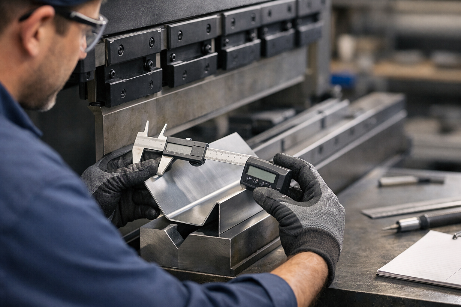
Bend allowance is a fundamental concept in sheet metal fabrication that accounts for the material stretch during bending. When a flat sheet is bent, the metal fibers on the outer radius stretch while those on the inner radius compress. Bend allowance helps engineers calculate the correct length of the flat pattern before bending, ensuring the final part dimensions are accurate.
Why Bend Allowance Matters on the Shop Floor
Accurate bend allowance calculations prevent costly errors such as parts being too short or too long after bending. This saves time, reduces scrap, and improves assembly fit. For example, if a technician neglects bend allowance, a box flange might not fit properly, requiring rework or remanufacture. Understanding bend allowance also aids in programming CNC press brakes and laser cutters for precise operations.
Key Terms: Bend Allowance, Bend Radius, and K-Factor
- Bend Allowance (BA): The length of the neutral axis in the bend area, representing the amount of material needed to accommodate the bend.
- Bend Radius (R): The radius of the inside curve of the bend.
- K-Factor: The ratio of the neutral axis location to the material thickness; it helps calculate bend allowance by identifying the stretch point inside the material.
The neutral axis lies between the inside and outside fibers and experiences no length change. Its position depends on material properties and bend method.
Calculating Bend Allowance: The Basic Formula
A commonly used formula for bend allowance is:
BA = (/180) Bend Angle (R + K T)
Where:
- BA = Bend Allowance
- Bend Angle in degrees
- R = Inside Bend Radius
- K = K-Factor (typically 0.3 to 0.5)
- T = Material Thickness
For example, bending a 0.125-inch thick aluminum sheet with a 1/8-inch bend radius at a 90-degree angle and a K-factor of 0.4:
BA = (3.1416/180)  90  (0.125 + 0.4  0.125)
BA  1.5708  (0.125 + 0.05) = 1.5708  0.175 = 0.275 inches
This means 0.275 inches of material length accommodates the bend.
Practical Example: Developing a Flat Pattern
Imagine fabricating a simple U-shaped channel with two 90-degree bends. Each leg is designed to be 2 inches long, with 0.125-inch thick steel and a 0.125-inch bend radius.
To find the flat length:
- Calculate bend allowance for one bend (using K-factor 0.44 for steel):
BA = (/180) 90 (0.125 + 0.44 0.125) = 1.5708 (0.125 + 0.055) = 1.5708 0.18 = 0.283 inches
- Total flat length = leg 1 + leg 2 + 2 BA = 2 + 2 + 2 0.283 = 4.566 inches
This flat length ensures after bending, the channel legs measure 2 inches each, accounting for material stretch.
Bend Deduction vs. Bend Allowance
Bend deduction is another term related to flat pattern calculations. It represents the difference between the sum of flange lengths and the flat length. While bend allowance adds the neutral axis length for the bend, bend deduction subtracts the bend area to find flat length directly.
Bend deduction and bend allowance are related by this formula:
Bend Deduction = Flange 1 + Flange 2 - Bend Allowance
Understanding both helps in cross-checking measurements and ensuring accuracy.
Factors Affecting Bend Allowance
Several variables influence bend allowance calculations:
- Material Type: Different metals stretch differently; aluminum and stainless steel have different K-factors.
- Material Thickness: Thicker materials require more allowance due to greater stretch.
- Bend Radius: Larger radii reduce material stress but increase allowance.
- Bend Angle: More acute bends increase allowance.
Manufacturers often provide K-factor charts or software tools for specific materials and thicknesses.
Using Software and Tools
Many CAD and CAM programs integrate bend allowance calculations, allowing engineers to input material data and bend parameters for automatic flat pattern generation. However, shop-floor personnel should understand the underlying concepts to verify and adjust results.
Simple calculators and spreadsheets can also assist in quick checks. Always cross-reference with physical test bends and manufacturer guidelines.
Tips for Accurate Bend Allowance Application
- Always measure the actual bend radius on tooling since tooling wear can change radii.
- Perform test bends on sample material to validate calculations.
- Record and update K-factors based on real-world results for your shop’s materials and processes.
- Communicate clearly with operators and programmers about bend parameters.
Conclusion
Sheet metal bend allowance is a critical factor in ensuring parts are fabricated to correct dimensions. By understanding the concepts, formulas, and practical considerations, engineers and technicians can reduce errors and improve efficiency. Accurate allowance calculations combined with real-world testing and adjustments lead to better quality and lower costs in sheet metal manufacturing.
Always consider material properties, tooling conditions, and bend angles when planning your flat patterns. With experience and careful measurement, bend allowance becomes a reliable tool for successful fabrication.

