This guide explains step-by-step how to confidently read simple circuit schematics, helping hobbyists and DIY enthusiasts understand electronic diagrams without guesswork.
Understanding basic electronic schematics is essential for anyone interested in building or repairing circuits. A schematic diagram shows the components of a circuit and how they connect, but beginners often find these diagrams confusing. This article breaks down the process of reading simple circuit schematics without guessing, using practical examples and clear explanations.
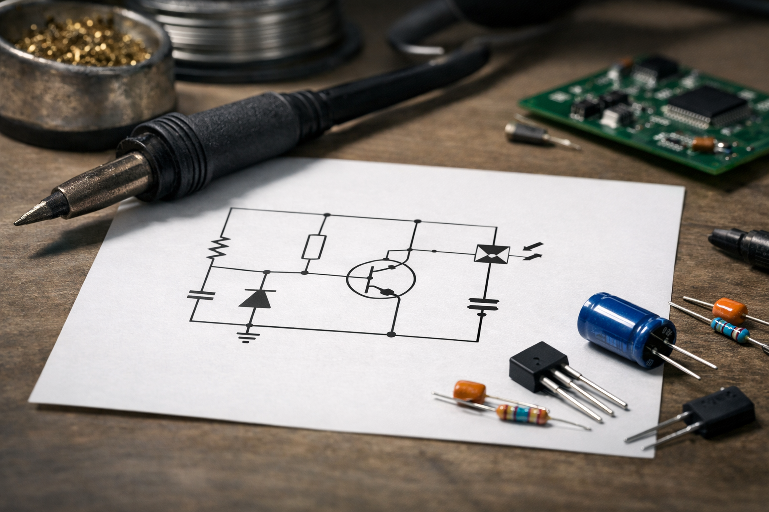
What Is a Circuit Schematic?
A circuit schematic is a graphical representation of an electrical circuit. It uses standardized symbols to show components like resistors, capacitors, switches, and power sources, along with lines to represent wires or connections. Unlike a physical wiring diagram, a schematic focuses on the function and relationships between components rather than their physical placement.
Familiarize Yourself with Common Symbols
Before reading any schematic, you need to recognize the symbols used. Here are some of the most common ones:
- Resistor: A zigzag line or a rectangle
- Capacitor: Two parallel lines, one may be curved for polarized capacitors
- Battery or Power Source: A pair of lines, one longer (positive) and one shorter (negative)
- Switch: A break in a line with a pivoting line segment
- Ground: A set of three descending lines or horizontal lines
- LED (Light Emitting Diode): A diode symbol with arrows pointing outward
You can find comprehensive symbol charts in electronics textbooks or online resources. Familiarity with these symbols is key to understanding schematics.
Understand the Flow of Current
Most schematics are drawn with the positive voltage source at the top and ground at the bottom. Current typically flows from the positive terminal through the circuit components and back to ground or the negative terminal. By following this flow, you can trace the path the electrical current takes.
Step-by-Step Approach to Reading a Schematic
- Identify the Power Source: Locate the battery or power supply symbol. This is the starting point.
- Trace the Connections: Follow the lines from the power source to other components.
- Recognize Components and Their Values: Check for component labels such as R1 (resistor 1) along with values (e.g., 1k).
- Look for Nodes and Junctions: Points where multiple lines meet indicate connections.
- Note the Ground Connection: It’s the reference point for voltage in the circuit.
Practical Example: Reading a Simple LED Circuit
Consider a simple circuit with a battery, resistor, switch, and LED:
- The battery symbol shows the positive and negative terminals.
- A line connects the positive terminal to a resistor labeled R1 with a value of 220.
- From the resistor, a line goes to a switch symbol.
- The switch connects to the anode of the LED symbol.
- The LED’s cathode connects back to the battery’s negative terminal (ground).
By following these connections, you understand that pressing the switch allows current to flow from the battery, through the resistor (which limits current), through the LED (which lights up), and back to the battery.
Tips for Avoiding Common Mistakes
- Don’t Assume Physical Layout: Schematic diagrams show connections logically, not physically. Components may be drawn apart even if they’re close in the real circuit.
- Check Component Orientation: Some components like diodes and electrolytic capacitors have polarity. Pay attention to the direction indicated.
- Verify Connections at Junctions: A dot indicates a connection; crossing wires without a dot usually do not connect.
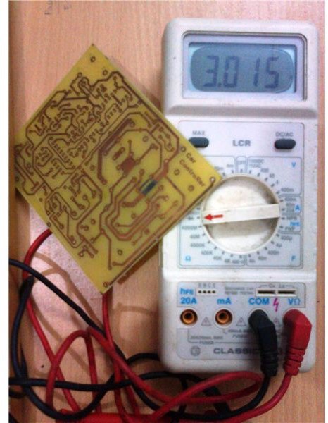
Using Multimeters Alongside Schematics
A multimeter can help verify the actual circuit matches the schematic:
- Use the continuity mode to check if two points are connected.
- Measure voltage at different points to confirm correct power flow.
- Test resistor values to ensure components match the schematic.
This practical verification reinforces your understanding and helps catch wiring errors.
When to Consult Professionals and Documentation
While reading simple schematics is straightforward, complex or safety-critical circuits require professional knowledge. Always refer to manufacturer datasheets for specific components and follow local electrical codes. For high-voltage circuits or those involving hazardous conditions, consult qualified electricians or engineers.
Summary
Reading simple circuit schematics becomes manageable by learning common symbols, understanding current flow, and methodically tracing connections. Using examples like an LED circuit helps visualize the process. Always double-check component orientations and connections, and use tools like multimeters to confirm your understanding. With practice, reading schematics will become a reliable skill that supports your electronics projects and repairs.
By following these steps, hobbyists and DIY enthusiasts can confidently interpret circuit diagrams without guesswork, enabling safer and more successful electronics work.