We have already discussed the various types of flip-flops. Read here to learn about Master-slave flip-flops. How are master-slave flip-flops different from other types of flip-flops? Where are they used in digital electronic circuits?
Introduction
In previous articles we discussed the JK flip-flop and its undesirable operation. When J=1 and K=1, there is a restriction on pulse width due to toggle operation (where output complements again and again until clock pulse goes to 0). This restriction can be bumped off using the Master-Slave Flip-flop.
Let us discuss the operation of master-slave flip-flops in detail.
Master-Slave Flip-Flops
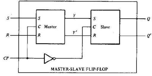
A master-slave flip-flop is normally constructed from two flip-flops: one is the Master flip-flop and the other is the Slave. In addition to these two flip-flops, the circuit also includes an inverter. The inverter is connected to clock pulse in such a way that the inverted CP is given to the slave flip-flop. For example, if the CP=0 for a master flip-flop, then the output of the inverter is 1, and this value is assigned to the slave flip-flop. In other words if CP=0 for a master flip-flop, then CP=1 for a slave flip-flop.
A master-slave flip flop can be constructed using any type of flip-flop which forms a combination with a clocked RS flip-flop, and with an inverter as slave circuit.
An RS master-slave flip-flop consists of two RS flip-flops; one is the master flip-flop and the other a slave. The inverted CP is given to the slave flip-flop. Now when CP=0, the master flip-flop is disabled. So the external inputs R and S of the master flip-flop will not affect the circuit until CP goes to 1. The inverter output goes to 1 and it enables the slave flip-flop. The output Q=Y and Q’=Y’.
When CP=1, the master flip-flop is enabled and the slave flip-flop remains isolated from the circuit until CP goes back to 0. Now Y and Y’ depends on the external inputs R and S of the master flip-flop.
Assume that the flip-flop is in a clear state and no clock pulse is applied to the circuit. The external inputs given are S=1 and R=0. This input will not affect the state of the system until the CP=1. Now the next clock pulse applied should change the state to SET state (S=1, R=0). During the clock pulse transition from 0 to 1, the master flip-flop goes to set state and changes the output Y to 1. However this does not affect the output of the system since the slave flip-flop is isolated from the system (CP=0 for slave). So no change is observed at the output of the system.
When the CP returns to 0, the master flip-flop is disabled while the slave is enabled. So the information from the master is allowed to pass through to the slave. Since Y=1, this changes the output Q to 1.
In a master slave flip-flop it is possible to change the output of the flip-flop and the external input with same clock pulse. This is because the external input S can be changed at the same time while the pulse goes through its negative edge transition. When CP=0, change in external input S would not affect the state of the system. From this behavior of the master slave flip-flop it is quite clear that the state change in flip-flops coincide with the negative edge transition of the pulse.
Negative edge transition means an inverter is attached between the CP terminal and the input of the slave. In positive edge triggered master slave flip-flops an additional inverter is attached between the CP terminal and the input of the master. Such flip-flops are triggered with negative pulses. Negative edge of the pulse affects the master and positive edge affects the slave.
JK Master-Slave flip-flop
Let us discuss the construction and working of the JK master slave flip-flop. A JK master slave flip-flop can be constructed using NAND gates. It is constructed using two flip-flops. Gate I to 4 represents master flip-flop and gate 5 to 8 represents slave flip-flop. Gate 9 represents the inverter.
During the positive edge of the flip-flop, the information from external inputs J and K is passed through to the master flip-flop. It is held there until the negative edge transition of the flip-flop occurs. Then the information is passed to the slave, clocked RS flip-flop, and the output is observed.
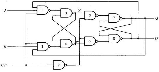
Usually the clock pulse is 0 at start, so the values of J and K will not affect the state of the system, and the master flip-flop is isolated. But the output of gate 9 is 1, hence the slave flip-flop provides the output Q=Y and Q’=Y’. When the clock pulse goes to 1, the slave is isolated; J and K inputs may affect the state of the system. The slave flip-flop is isolated until the CP goes to 0. When the CP goes back to 0, information is passed from the master flip-flop to the slave and output is obtained.
Current digital systems make heavy use of master-slave flip-flops. The output of some master-slave flip-flops is given as an input to the other master-slave flip-flops. If the clock pulse inputs to all master-slave flip-flops are synchronized then at the beginning of each clock pulse, some of the master elements changes state. But the output remains in the previous state without any change (because slave is isolated and disabled). Again when CP returns to 0, the output changes sate and the master flip-flops are disabled. So the new state of output does not have any effect on the master input until CP=1. Therefore both the state of the system and the input elements can be changed simultaneously with a single clock pulse. So the binary content of one flip-flop can be transferred to second and the content of second can be transferred to first simultaneously during the same clock pulse.
The master-slave flip-flops are widely used in MEMORY REGISTERS.
Image and Content Credits:
Digital logic design by “Morris Mano”
Digital electronics by “P.S.Manoharan”


