About Electrical Circuit Theory
Approaches to Circuit Analysis
There are few theorems that can be applied to find the solution of electrical networks by simplifying the network itself or it can be used to calculate their analytical solution easily. The electrical circuit theorems can also be applied to A.C systems, with only one difference: replacing the ohmic resistance of the D.C system with impedance.
There are two general approaches to network analysis:
1. The Direct Method:
In this method, the network is left in its original form while determining it different voltages and currents. Such method are usually restricted to fairly simple circuits and include Kirchhoff’s law, loop analysis, nodal analysis, superposition theorem, compensation theorem, and reciprocity theorem, etc.
2. The Network Reduction Method:
In this method, the original network is converted into a much simpler equivalent circuit for a rapid calculation of different quantities. This method can be applied to a simple as well as complicated network. Examples of this method are: Delta/Star and Star/Delta conversion, Thevenin’s theorem, and Norton’s theorem, etc.
Common Terms used in Circuit Theory
- A circuit is a closed conducting path through which an electrical current either flows or is intended to flow. A circuit consists of active and passive elements.
- Parameters are the various elements of an electrical circuit (for example, resistance, capacitance, and inductance).
- Linear circuit – a circuit in which the parameters are constant with time, do not change with voltage or current, and obey Ohm’s law. In a non-linear circuit the parameters change with voltage and current.
- A passive network is a one which contains no source of EMF.
- An active network is a one which contains one or more sources of EMF.
- A bilateral circuit is one whose properties or characteristics are same in either direction of current. Example: the usual transmission line is bilateral.
- A unilateral circuit is that circuit in which properties or characteristics change with the direction of operation. Example: a diode rectifier can rectify only in one direction.
- A Node is a point in a circuit where two or more circuit elements are connected together.
- Branch is a part of a network which lies between two nodes.
- Loop is a closed path in a circuit in which no element or node is encountered more than once.
- Mesh is a loop that contains no other loop within it.
Parameters of Electrical Circuit:
Series and Parallel Electrical Circuits
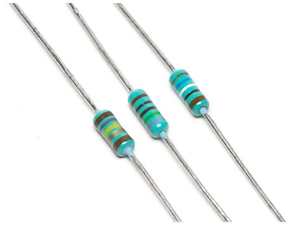
1.Resistance circuits:
- Resistance in Series:
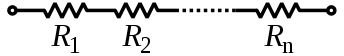
When some resistor of R1, R2,….Rn are joined end-on-end as shown, they are said to be connected in series. It can be proved that the equivalent resistance or total resistance between them is equal to the sum of the three individual resistances.
In a series circuit remember that Current is the same through all the conductors but Voltage drop across each is different due to its difference resistance. The total resistance R is equal to
R = R1 + R2 + ……+ Rn.
- Resistance in Parallel:
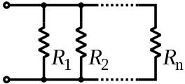
When some resistors of R1, R2 ….Rn are joined in parallel as shown in the figure, voltage drop is the same across all the resistors, but the current in each resistor is different and it is given by ohms law. The total current is the sum of the three separate currents so the Equivalent resistance R of all the resistors in Parallel is equal to the reciprocal of the total resistance of the reciprocals of the resistance of their individual resistances.
1/R = { (1/R1) +(1/R2) +…..+ (1/Rn) }
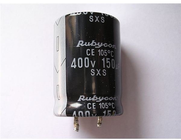
2. Capacitive Circuits:
- Capacitor in Series:

When some of the capacitors, of C1, C2…..Cn are connected in series as shown in the figure, then the Equivalent Capacitance C of capacitors in series is equal to the reciprocal of the sum of the reciprocals of their individual capacitances.
1/C = { ( 1/C1) + ( 1/C2) +…..+(1/Cn)}
- Capacitor in Parallel:

When some Capacitors, of C1, C2 ….Cn are joined in parallel as shown in the figure, then the Equivalent capacitance of all the capacitors connected in parallel is equal to the sum of the individual capacitance.
C = C1+C2+……+Cn
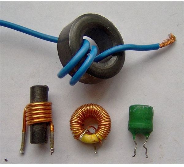
3. Inductive Circuits:
- Inductors in Series:

When some of the Inductors, of L1, L2…..Ln are connected in series as shown, then the Equivalent Inductance L is equal to the sum of their individual inductance connected in the circuit.
L = L1 + L2 +…..+ Ln
- Inductors in Parallel:

When some of the Inductors, of L1, L2 …..Ln are connected in parallel as shown, then the Equivalent inductance L of inductors in parallel is equal to the reciprocal of the sum of the reciprocals of their individual inductance.
1/L = { ( 1/L1) + ( 1/L2) +…..+(1/Ln)}
Network Theorems:
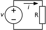
1. Ohm’s Law:
These electrical theorems are applied to the electrical network to simplify and to find the solution of the electrical network.
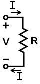
The voltage across a resistance is equal to the product of the resistance and the current flowing through it.
Voltage = Resistance × Current.
2. Kirchhoff’s Laws:
These laws are more comprehensive than the Ohm’s law and are used for solving electrical networks which may not be readily solved. It is mainly useful in determining the equivalent resistance of a complicated network of conductors and for calculating the currents flowing in the various conductors.
- Kirchhoff’s Current Law:
It states that “In any electrical network, the algebraic sum of the current meeting at a point (or junction) is zero”.
Meaning: It simply means that the total current leaving a junction is equal to the total current entering that junction.
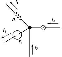
Incoming current = Out going current.
- Kirchhoff’s Voltage Law:
The algebraic sum of the product of currents and resistance in each of the conductors in any closed path (or mesh) in a network plus the algebraic sum of the EMF in that path is zero.
Meaning: It simply means that, if we start from a particular junction and go round the mesh till we come back to the starting point, then we must be at the same potential with which we started.
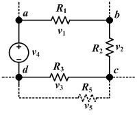
Image Credit:
https://en.wikipedia.org/wiki/Resistor
https://en.wikipedia.org/wiki/Capacitor
https://en.wikipedia.org/wiki/Inductor
https://en.wikipedia.org/wiki/Series_and_parallel_circuits
https://en.wikipedia.org/wiki/Ohm%27s_law
https://en.wikipedia.org/wiki/Kirchhoff%27s_circuit_laws#Kirchhoff.27s_voltage_law