I Learned from That: Opening Drain Valve Leads to Catastrophic Failure of Boiler Tubes in new Power Plant
This happened almost ten years ago. A simple but wrong operational procedure led to a catastrophic boiler failure and a repair that cost a few million dollars.
We had just erected and commissioned a circulating fluidized bed boiler for an industrial plant in Southeast Asia. The boiler was a state of the art CFBC and almost the largest boiler in the region at that time. It was capable of producing nearly 400 tons per hour of steam for power generation and utility purposes, firing coal and biomass with superheated steam at a pressure of 140 bar and temperature of 540°C.
A basic understanding of a boiler is required to understand what went wrong.
Furnace
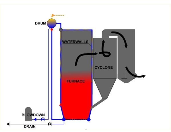
The furnace of a modern boiler is made of welded tubes called membrane panels. The carbon steel tubes of diameter 60.3 mm welded at a pitch of 75 mm forms the boiler furnace with a height of 40 meters, width of 12 meters, and depth of 8 meters. The heat transfer area was around 1700 square meters. The heat in the furnace transfers to the water in these tubes to produce steam. The furnace is at temperatures in the range of 800°C to 1000 °C. The water flowing through the tubes keeps the tube metal temperatures well below the deformation temperatures. If there is no water flow in these tubes, the tubes will overheat and fail. This is true for any vessel that boils water. Even in your house, if you heat a pot or a pan without water it will twist out of shape.
Circulation
How does water circulate in these tubes? Water flows into these tubes from the boiler drum located at the top of the furnace through large pipes called “down comers.” Steam starts forming in these tubes as it absorbs the heat from the furnace. The steam water mixture is at a lower density than the water in the down comers. Consider this like a “U” tube having the down comer filled with denser fluid (water) and the water wall tubes with lighter fluid (a water and steam mix). Both legs connect to the top drum. This density difference between the two legs causes circulation in these tubes.
Blowdown
The steam and water mixture from the water walls enter the drum, the steam separates, and the water recirculates back. The chemicals in the water do not evaporate and remain in the water. Continuous circulation of the water increases the concentration of the chemical content. Continuous removal of a part of the water from the bottom of the drum by a process called “blowdown” controls the concentration level.
Drains
The water wall membrane panels connect to headers at the top and bottom. The down comers connect to the bottom headers distributing the water evenly to the tubes. The top headers connect to the drum through riser tubes that carry the water steam mixture to the drum. The bottom headers have drain pipes with valves. These manual operation valves are only for use during the initial operation for flushing and cleaning the headers or for filling or removing the water from the boiler.
The Incident
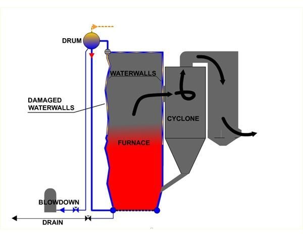
The incident occurred during the final stages of commissioning. The unit was operating at near full load at the maximum operating pressure. Because of higher than allowable concentration of chemicals in the drum, the commissioning engineer decided to use the water wall drains for blowdown for a short time. Since these were manual valves operating under high pressure differential, the quick open-close operation was not quick enough.
How long the valve was in open condition is unknown. This opening of the drains at the bottom headers had the effect of breaking the “U” tube effect and killing or reducing the flow of water through the tubes. This resulted in higher than acceptable metal temperatures in the water wall tubes. A few tubes failed, and the failure led to a unit outage. In the ensuing inspection, the extent of the damage was visible. The entire water wall on the front and sides of the furnace for almost the entire height was distorted into a wavy pattern.
Repair
Since the plant was in an electrically islanded facility, the power and steam was necessary to keep the plant production levels. The boiler was back in operation after replacement of the burst tubes- at a lower load and pressure with the waterwall distortion. Because this was a CFBC boiler, the sand and ash circulating in the furnace required quick replacement of these wavy tubes before any failures due to erosion took place. The boiler operated with this condition for almost six months until the replacement tubes were available at site. It took thirty days to replace the walls and another fifteen days to put the unit back into service.
Conclusion
One should know the design basics and do some critical thinking before attempting to do something that is not normally done.
This post is part of the series: I Learned from That! (Mechanical Engineering)
All professional engineers, after they have worked long enough, have stories about when things suddenly went disastrously wrong or presented a patently unsafe situation. They may have come on the scene later and had to perform an analysis of what happened and what could have prevented the incident.