Nonlinear Loads and Harmonics in Power Systems
Nonlinear Loads
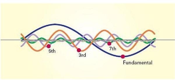
A nonlinear load in a power system is characterized by the introduction of a switching action and consequently current interruptions. This behavior provides current with different components that are multiples of the fundamental frequency of the system. These components are called harmonics. The amplitude and phase angle of a harmonic is dependent on the circuit and on the load it drives. For a fundamental power frequency of 60 Hz, the 2nd harmonic is 120 Hz, the 3rd harmonic is 180 Hz, and so on. The harmonic currents flow toward the power source through the path of least impedance.
Some examples of nonlinear loads that can generate harmonic currents are computers, fax machines, printers, PLCs, refrigerators, TVs and electronic lighting ballasts. Personal computers constitute nonlinear loads since they incorporate switched-mode power supplies. The PC current is mainly dominated by the third and fifth harmonic components. Current harmonics deteriorate the power factor of the system, what is the ratio between the average power of a certain load and the average power calculated for a pure resistive load with equal voltage amplitude. Differently from the reactive power drawn by a linear load, the harmonic currents cannot be corrected by the use of capacitors and inductors, but by the use of Harmonic Mitigating Transformers.
Current distortions can produce voltage distortions. When currents with harmonics flow through electrical generation systems and transmission lines, additional distortions take place because of the impedance of the electrical network.
Power systems that are conceived to operate at the fundamental frequency are susceptible to erroneous behavior as more and more nonlinear loads are connected to the network. Harmonics increase the resistances of the conductors due to skin effect and cause an abnormal neutral-ground voltage difference. The more nonlinear loads connected, the higher the overall sum of harmonics, though the total sum is less than the sum of the individual magnitudes. Harmonics can damage components like fuses and circuit breakers, and can cause utility meters to record wrong measurements.
Filters can be used when equipments are connected in a non-sinusoidal system. Nonlinear loads can be modeled, and these models can be used to evaluate the voltage and current harmonics in the loads.
The K-factor
There is great concern about the distribution transformers that supply the nonlinear loads, since they suffer from: (1) overheating of windings, insulation, and oil; (2) additional eddy current heating in metallic parts; (3) higher stress in tap changers, bushings, and cable-end connections. The overheating of general wiring due to skin and proximity effects is not so serious as the heating of the neutral conductor in a 3-phase system with a line-to-neutral connection. The harmonic spectrum of the current must be analyzed in order to determine the excess losses in transformers.
Transformers supplying nonlinear loads must have additional overcurrent protection. Linear loads that are supplied with harmonic voltage distortion draw a nonlinear harmonic current. The life of a motor is reduced due to overheating. Some equipment, like communications and data processing devices, may fail when connected to systems that contain a large amount of nonlinear loads and, consequently, harmonics.
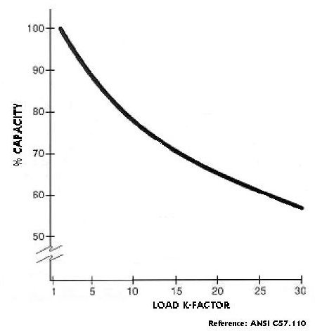
The K-factor is a rating system that was conceived to indicate how well a transformer can handle harmonics generated by nonlinear loads. A linear load provides a K-factor of 1 (one). The higher the K-factor, the greater the harmonic heating effects. The main objective of creating this indicative factor is to design a distribution transformer which can operate under certain conditions without life loss.
Harmonic Mitigating Transformers
Since harmonics cause much more problems than simply overheating the transformers, it is more appropriate to make use of a resource that is able to reduce the system voltage distortion. Harmonic Mitigating Transformers are efficient in solving overheating and the power quality problems generated by harmonics. The voltage distortion at the output is kept very low because of the cancellation of the harmonic magnetic fluxes within the transformer’s windings.
Guidelines for Reducing the Effects of Harmonics
The Institute of Electrical and Electronics Engineers (IEEE) prepared the guide “IEEE Recommended Practices and Requirements for Harmonic Control in Electrical Power Systems”, which provides guidelines for the power quality that the utility must supply and the users can deliver back to the power distribution system. The guide suggests corrections in the system that are able to eliminate or reduce specific orders of harmonics, such as line reactors and the use of a 12-pulse converter front-end.
References
VENKATESH, C. et al. Modelling of Nonlinear Loads and Estimation of Harmonics in Industrial Distribution System. 15th National Power Systems Conference, p. 592-597, 2008.
The Journal of Power Quality Issues & Solutions. Vol.1 No.2, 1995.
Harmonics in your Electrical System. White Paper. Eaton Corporation <www.powerware.com>.
HOEVENAARS, T. How the Harmonic Mitigating Transformer Outperforms the K-Rated Transformer. MIRUS International Inc. 1999.