Transformers - Transfer Power (as if) by Magic (Part II)
Introduction
If you have not read the first article of this series, I would suggest that you take a look at that first by clicking here. As I had mentioned in the first part, power is transferred between the primary and secondary circuits through the phenomenon of mutual inductance, so let us learn something about that.
Mutual Inductance
We learned about magnetic circuits in an earlier article and know from there that a current carrying conductor is surrounded by magnetic flux. Now suppose another conductor is placed in that magnetic field, what will happen? When the current in the first conductor changes it causes a corresponding variation in the associated magnetic flux, which will result in an induced emf in the secondary circuit.
This forms the basis of definition of mutual inductance which is defined as the phenomenon of emf being generated in one circuit when the current in the coupled circuit is varying. The formula which governs the generated emf is known as Faraday’s Law and it states that the emf induced in a circuit is directly proportional to the rate of change of magnetic flux through the circuit with time. Mathematically this law is expressed as
EMF = -N ∆BA/∆t
Where BA (B is the magnetic field, A is the area of the coil) stands for magnetic flux and t is time while N is the number of turns of the conductor. The negative sign denotes that the direction of the generated emf is such that the current generated tries to oppose the magnetic field producing it. This may seem quite paradoxical in that the current is trying to oppose the very source of its origin but it is known as Lenz’s law.
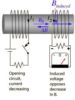
I also suggest that you take a good look at the diagram in figure 1 below as it beautifully depicts the phenomenon of mutual inductance in a pictorial format. As you can see from the picture, there are two independent circuits and when voltage is withdrawn from the circuit on the left hand side, it causes an emf in the right hand side circuits which tries to oppose that change.
Figure 1: Mutual Inductance
Application to a Transformer
I think you must have intuitively imagined by now as to how the above paragraph fits into the concept of a transformer. Since a transformer also consists of two conductors, which are in the form of coils wound around the core, if varying voltage (and hence varying current) is fed into one of the circuits (which is known as the primary circuit), it generates an emf in the other circuit (which is known as the secondary circuit). This should also make you understand why transformers work with AC voltages and not DC voltages. Because if the voltage and hence the associated current is steady (i.e. Direct Current), it would not cause any induced emf to be created in the secondary circuit. Of course there is a separate topic about DC inductance but that is much beyond the scope of this article and we might take it up later on in some other article.
In the next article of this series we will take this study a step further and learn how the Faraday’s law can be used to calculate the increase or decrease of voltage that can be achieved through a transformer and how it can be useful in different situations.
Suggested Readings
Transformers - Transfer (as if) by Magic (Part I)
AC & DC Circuits
References
Figure 1: Mutual Inductance
This post is part of the series: Transformers - Transfer Power (as if) by Magic
How do transformers work? This series will discuss the principles behind the functioning of the extremely useful devices.