Ship Hull Designs in Naval Architecture - An Overview
Introduction
The hull is one part of the ship that requires extra concern during design and construction. In the history of naval architecture, hull designs has evolved over a period of time, from cylindrical wooden shanks to steel columns. Engineers have been continuously innovating hull designs to provide greater structural strength. As hull is continuously in contact with water, it is under the effect of different types of forces acting at the same time. Not only that, a hull requires high durability and resistance to prevent structural damage in case of collision or grounding.
Naval architects use different methods for hull construction keeping in mind the purpose and type of ship. In this article we will have a look at the basic ship hull designs which are commonly used.
Terms in ship hull design
For understanding a hull structure, it is important to know the basic terms. We will quickly go through the basic terms that are required to understand a design.
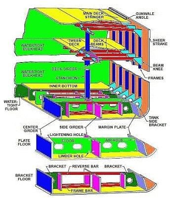
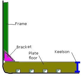
Frame- It is a steel plate that runs longitudinally or transversely throughout the hull structure. Frames are welded to the sides of the hull as shown in the figure. They form the basis of any design and all hull designs consist of frames.
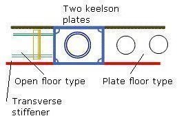
Plate Floor or Floor plate - A steel plate which is welded to the floor of the hull. Plate floors run longitudinally throughout the hull floor as shown in the figure.
Flanged Bracket -Triangular shaped Iron brackets that are welded where the two frames meet. They are attached to the margin plates to resist excessive bending stress.
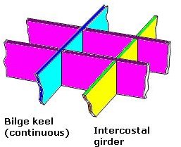
Side Girders - Inter coastal plates that are used to join two floor plates.
Keel plate - They are used to join floor plates to the keel of the ship.
The two main methods that are used for hull construction are :
- Transverse framing
- Longitudinal framing.
Transversally Stiffened
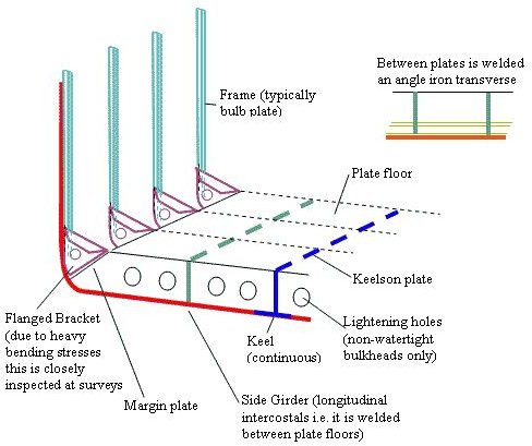
Though this hull design is outdated, it is still used for smaller ships of length less than 120 meters. In this design there is a plate floor every 3.05 meters and a frame every 1 meter. The frames run tranversally to the hull structure. The frames are joined together with the help of floor angle iron transverse. In this design every floor plate will have 3 frames. The frames are attached to the margin plates with the help of flanged bracket as shown in the figure.
Iron transverse is attached between two floor plates to provide additional support and increase structural strength. Refer the diagram for a better understanding of the design.
Longitudinally framed hull- For Tankers
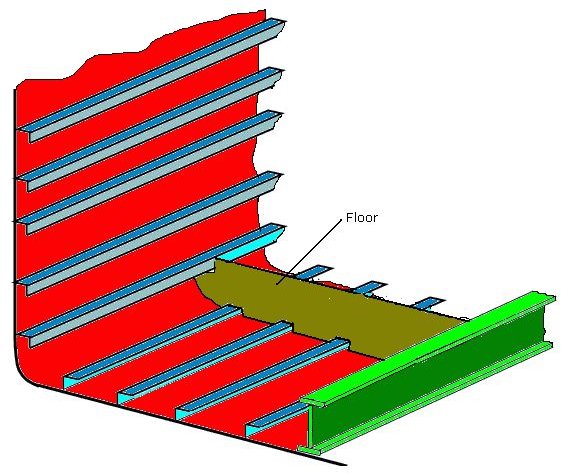
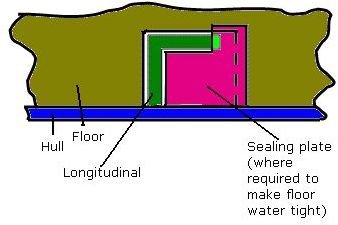
In longitudinal framing the frames are attached longitudinally to the floor plates instead of transverse. This helps to resist the bucking force in a much effective way. Frames( Vertical and horizontal frames) are joined at the intersection of two sides is the same way as in transverse design but with the help of web as shown in figure. Sealing plates are used wherever the floors are to be made water tight(Generally in tankers). They are welded to the longitudinal frames as shown in the figure.
Longitudinally framed hull-For Dry cargo
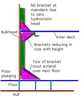
In Longitudinal framed hull for dry cargo, brackets are used to provide strength to the frame. The size of the brackets keeps on increasing as the height of the deck increases. Brackets are used to provide additional structural strength to the bulkhead as there are high number of inter-decks in ships used for dry cargo.
References
Practical ship design by D.G.M Watson
Ship Design for Efficiency and Economy (2nd ed.) by SCHNEEKLUTH, Herbert, and Volker BERTRAM
Image Credits
Images with permission of Brian Beattie of Marine Engineering Knowledge Website