Comparison of Theoretical Cycles of Marine Diesel Engines - Dual, Otto, and Diesel
Introduction
In these three articles we studied about Otto cycle, diesel cycle and dual cycle and looked at their thermal efficiency. In this article we will take a collective look at these three cycles in order to compare and contrast them, so that we can come to know the relative advantages and disadvantages of these cycles.
The 3 Cycles Compared
Firstly let me make it clear that the comparison between these cycles is not a straightforward thing like saying “this is better than that”, because there are many parameters involved. Some of these parameters are compression ratio, peak pressure, peak temperature, heat added, heat rejected and so forth. Since each of these has a different effect on the cycle we can only compare when a few of these parameters are kept constant while others are allowed to vary. This would give rise to a number of combinations under which the performance could be gauged. In this article we will study one such comparison and other comparisons in future articles for sake of simplicity. In the scenario considered here the compression ratio and heat rejection is kept constant for all cycles. The P-V and T-S diagrams of these three cycles are drawn simultaneously as described below.
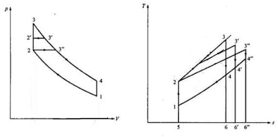
In the above diagrams the following are the cycles
- Otto cycle: 1 – 2 – 3 – 4 – 1
- Dual cycle: 1 – 2 – 2’ – 3’ – 4’ – 1
- Diesel cycle: 1 – 2 – 3” – 4” – 1
Remember that we are assuming constant compression ratio for all three cycles which is given by V1/V2
The other parameter which is constant is the heat added to the cycle which is given by the following in each case as per the T-S diagram
- Otto cycle: Area under 5 – 2 – 3 – 6
- Dual cycle: Area under 5 – 2 – 2’ – 3’ – 6’
- Diesel cycle: Area under 5 – 2 – 3” – 6”
The heat rejected is different in each case and can be established from the T-S diagram as follows
- Otto cycle: Area under 5 – 1 – 4 – 6 say q1
- Dual cycle: Area under 5 – 1 – 4’ – 6’ say q2
- Diesel cycle: Area under 5 – 1 – 4” – 6” say q3
It can also be seen from the same diagram that q3>q2>q1
We know that thermal efficiency is given by 1 – heat rejected/heat supplied
Since heat supplied is same and we know the order of heat rejected, we can combine this information to conclude that
Thermal efficiency of these engines is of the following order
Otto>Dual>Diesel
Just remember that though Otto fairs better in this comparison in actual practice the level of thermal efficiency cannot be realized due to maximum pressure considerations.
This was the comparison with constant heat addition and compression ratio. Similar comparisons can be done by using constant compression ratio and heat rejected combination as well as other parameters as we will see in next articles.