Troubleshooting fuel pump problems - Learn about the working of fuel pumps
Introduction
We have been talking about various components of a marine engine right from the bedplate to the piston, connecting rod and so forth. In this article we will learn about one very important component which is necessary for engine operation. As you know the engine requires fuel to run, and the same needs to be supplied under pressure. This is necessary to ensure smooth running and efficient operation of the engine. The component which fulfills this purpose is known as the fuel pump.
The purpose of the fuel pump is to convey the fuel reaching from its fuel tank into the individual cylinders, under the requisite high pressure in order to ensure good atomisation and good combustion. Troubleshooting fuel pump problems is an important part of a marine engineer’s job and it is easier to carry out the same once the working of the same is understood in a proper manner. In the subsequent sections we will take a detailed look at how it works
Fuel Pump
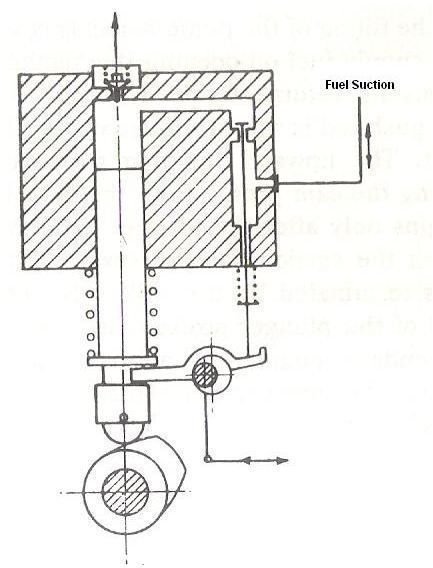
Fuel pumps come in various shapes and sizes and of various types. But if you understand the working principle of at least one of the pumps, others should follow suit. In this article I will explain the working of a typical valve controlled fuel pump. You will be in a better position to understand the text below if you correlate it with the adjacent diagram.
The pump plunger is moved upwards by the two piece cam through the roller and the guide plunger. A spring forces the guide plunger with the roller down on to the cam, while a second spring presses the pump plunger on to the guide plunger, returning the latter.The suction valve is controlled by spring loaded pins. Pins, which is of adjustable length, obtains motion from the guide plunger through the lever with unequal arms, which rests on the eccentric of the regulating shaft.
When the roller lies on the base circle of the cam, the pump plunger is in its bottom position and the suction valve is closed. As the roller runs up on the cam the guide plunger, pump plunger and the control pins move upwards. As the suction valve is closed, the fuel is forced through the automatic discharge, non return valve and discharge pipe into the fuel valve, from where it is injected into the cylinder. As the plunger stroke increases, the control pins also move downwards, finally lifting the suction valve from its seat. Discharge ceases at this moment and injection into the cylinder is terminated. The plunger now conveys the fuel back into the suction space. On the downward motion of the plunger the space which becomes free gets filled with fuel through the suction valve, this fuel flowing into the pump under pressure (either static pressure or pressure from the fuel transfer pump)
The distance travelled by the pump plunger from the moment discharge commences until the end of discharge with the lifting of the suction valve is called the effective delivery stroke.
Rotation of the regulating shaft alters the height of the fulcrum of the liner with unequal arms, resulting in the suction valve opening earlier or later. This in turn causes all the pumps to deliver greater or lesser quantity. the engine load which corresponds to discharge quantity can be read off from the load indicator. At a particular setting of the load indicator all the pumps of an engine are adjusted to exactly the same effective delivery stroke by means of adjustable control pins
Please note….I am currently in the process of drawing the diagrams on tigercad…so will be uploading images soon..
Image Credits
Pallas, J.L. (2006) Marine Diesel Engines: Maintenance and Repair Manual. New York: Sheridan House Inc